EasyManua.ls Logo

Pioneer LaserVision LD-V4200 User Manual

Pioneer LaserVision LD-V4200
41 pages
To Next Page IconTo Next Page
Page #1 background imageLoading...
Page #1 background image
1
PION
•·
••
· · ·· - ·
··
-
...
. . . .
..
...
......
«••-
-
••
••
••
-··
· ·
··
••
••
...
..
••
••
••
-
•••
•••••
••••
- -
'.
. ••
•••••••••
- - . . . . . .
..
-
·-
· · - -
·-
- ·
••
•••
- -
~--
- · . . . .
......
- - -
··
..
- - ••
·-
-
..
CIRCUIT
&
MECHANISM
DESCRIPTIONS
REPAIR &
ADJUSTMENTS
LASERVISION
PLAYER
.
ORDER
NO.
ARP1260-A
Laser
Vision
This service manual
is
applicable
to
the
KUC
type.
As
to
the
circuit and mechanism descriptions, please refer
to
the
LD-707
service manual
(VRT-060).
As
to
the
remote
control
unit
(RU-V101
),
please refer
to
the
RU-V101
service manual
(ARP1258).
CONTENTS
1.
SPECIFICATIONS
...................................................... 2
2.
OPERATION
OF
REMOTE
CONTROL
UNIT
(OPTION).................................................................... 3
3.
PANEL
FACILITIES.................................................... 4
4.
DISASSEMBLY.......................................................... 6
5.
P.C.B.
LOCATIONS.................................................... 8
6.
OVERALL
CONNECTION
. DIAGRAM...................... 9
7.
SCHEMATIC
DIAGRAM
AND
P.C.B.
PATTERNS
..
11
7.1
LSFB,
RECB,
LMCB,
DRVB
AND
FMPB
ASSEMBLY
........................................................
11
7.2
PICK-UP
AND
PREB
ASSEMBLY
....................
15
7.3
SRVB
(SPDL)
AND '
BLMB
ASSEMBLY
..........
19
7.4
SRVB
(FTS,
CONT)
ASSEMBLY
......................
23
7
.5
SRVB
(TBC)
ASSEMBLY
..................................
27
7.6
DEMB
AND
RLYB
ASSEMBLY
.................
.......
31
.
7.7
PWID,
KEYB
AND JACK
ASSEMBLY
...........
35
8.
ELECTRICAL
PARTS
LIST
....................................
....
39
9.
REPLACING
THE
PICK-UP
.......................................
44
10.
MECHANICAL
ADJUSTMENTS ..............................
45
11.
ELECTRICAL
ADJUSTMENTS ................................
52
12.
ICS
AND
TRANSISTORS
.........................................
58
13.
EXPLODED
VIEWS
AND
PARTS
LIST
...................
60
13.1
EXTERIOR
AND
FRONT
VIEW
........................
60
13.2
TOP
VIEW
..........................................................
62
13.3
BOTTOM
VIEW
.................................................
64
13.4
MECHANISM
VIEW
..........................................
66
13.5
PICK-UP
VIEW
...................................................
68
14.
PACKING
....................................................................
70
15.
SAFETY
INFORMATION
...........................................
71
PIONEER
ELECTRONIC
CORPORATION
4-1.
Meguro
1-Chome,
Meguro-ku,
Tokyo
153,
Japan
PIONEER
ELECTRONICS
SERVICE
INC.
P.O.
Box
1760,
Long
Beach,
Ca
l
ifornia
90B01
U.S.A.
TEL:
C213J
420-5700
PIONEER
ELECTRONIC
CEUROPEJ
N.V.
Keetberg
l
aan
1,
2740
Beveren,
Belgium
TEL:
03/775
·
2B
·
OB
PIONEER
ELECTRONICS
AUSTRALIA
PTV.
LTD
.
17B-1B4
Boundary
Ro
7~
rside.
Victoria
3195,
Australia
TEL:
C03J
590-9911
1
. \
\~
Fl
©
NOV.
1986 Printed in
Japan
Question and Answer IconNeed help?

Do you have a question about the Pioneer LaserVision LD-V4200 and is the answer not in the manual?

Pioneer LaserVision LD-V4200 Specifications

General IconGeneral
BrandPioneer
ModelLaserVision LD-V4200
CategoryCD Player
LanguageEnglish

Summary

1. Specifications

General Specifications

Player and disc specifications, dimensions, weight, and power requirements.

Video and Audio Output

Details on video and audio output levels and terminals.

Functions and Terminals

Lists player functions, remote control operations, and connection terminals.

Accessories

Lists the accessories included with the player.

2. Remote Control Unit Operation

Preparation and Key Functions

Steps for preparation and explanation of remote control key functions.

3. Panel Facilities

Front Panel Controls and Indicators

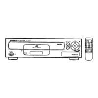
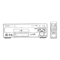
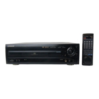
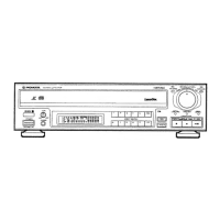
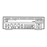
Details front panel controls, indicators, and display functions.

External Connections and Switches

Describes function switch cover, EXT CONT terminal, and KEY LOCK indicator.

Rear Panel Connections

Output Terminals and EFM Out

Describes EFM OUT and VIDEO/AUDIO output terminals.

Interface Connector

Details the serial interface connector for computer connection.

Front Panel Key Operations

Explains the functions of PLAY, STILL/STEP, REJECT, and SCAN keys.

4. Disassembly

Disassembly Steps

Bonnet, Bottom Plate, and Disc Table Removal

Instructions for removing the bonnet, bottom plate, and disc table.

Front Panel and Mechanical Section Disassembly

Steps for removing the front panel and disassembling mechanical parts.

5. PCB Locations

8. Electrical Parts List

9. Pick-up Replacement

10. Mechanical Adjustments

10.1 Tools and Jigs Required

Lists essential tools and jigs required for mechanical adjustments.

10.2 Adjustment Precautions

Provides crucial precautions for handling test discs and servos.

10.3 Test Mode Operation

Details how to enter and use the player's test mode.

10.4 Test Mode Functions and Exit

Describes additional test mode functions and how to exit safely.

10.5 Preparations for Adjustment

Steps to prepare the player for adjustment procedures.

10.4 FOCS Offset Adjustment

10.5 Grating Coarse Adjustment

10.6 TRKG Error Balance Adjustment

10.7 SLDR Shaft Level Adjustment

10.8 Pick-up Tilt Adjustment

10.9 FOCS Error Balance Adjustment

10.10 Tilt Sensor Tilt Adjustment

10.11 Grating Fine Adjustment

10.12 TRKG Loop Gain Adjustment

10.13 FOCS Loop Gain Adjustment

10.14 RF Level Adjustment

10.15 Inside Position Detection Adjustment

10.16 Outside Position Detection Adjustment

12-inch Outside Detection

Adjust VR9 for 12-inch outside position detection.

8-inch Outside Detection

Adjust VR10 for 8-inch outside position detection.

10.17 Other Adjustments

Disc Clamp Switch Position Adjustment

Procedure to adjust the disc clamp switch position.

11. Electrical Adjustments

Modulated Video Level Adjustment

Adjusts the modulated video level.

1H Delay Video Signal Adjustment

Adjusts the 1H delay video signal.

Audio Signal Level Adjustment

Adjusts the audio signal level.

11.2 SRVB Assembly

TBC Offset Adjustment

Procedure to adjust the TBC offset.

TBC Video Level Adjustment

Procedure to adjust the TBC video level.

Starting Oscillation Frequency Adjustment

Adjusts the starting oscillation frequency.

VCO Center Frequency Adjustment

Adjusts the VCO center frequency.

Time Axis Error Detection Adjustment

Adjusts time axis error detection.

VCO Circuit Center Frequency Adjustment

Adjusts VCO circuit center frequency.

Sync Gate Timing Adjustment

Adjusts sync gate timing.

Burst Gate Timing Adjustment

Adjusts burst gate timing.

Color Phase Correction Adjustment

Adjusts color phase correction.

PD0011 Clock Frequency Adjustment

Adjusts PD0011 (IC202) clock frequency.

12. ICs and Transistors

13. Exploded Views and Parts List

13.1 Exterior and Front View

Exploded view and parts list for exterior and front components.

13.2 Top View

13.3 Bottom View

13.4 Mechanism View

13.5 Pick-up View

Installing the Head Assembly

14. Packing

15. Safety Information

1. Safety Precautions

General safety precautions for customers and technicians.

Leakage Current Check

Procedure to measure and verify leakage current.

2. Product Safety Notice

Important notice regarding safety-related replacement parts.

Related product manuals