Do you have a question about the Pioneer MVH-355BT and is the answer not in the manual?
General precautions for servicing the unit safely and according to regulations.
Detailed technical specifications for the MVH-350BT/XMEW5 and MVH-150UI/XMEW5 models.
Essential checks to perform after completing service to ensure product quality.
Step-by-step flowchart for diagnosing power-on and initial operation issues.
List of error messages, their causes, and recommended actions for USB/iPod and Bluetooth devices.
Guide for updating the MCU software using USB memory, including the operation flow and error handling.
Schematic diagram for the Tuner Amp Unit, including PCB layout references.
Schematic diagram detailing the connections and components of the Keyboard Unit.
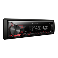
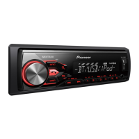
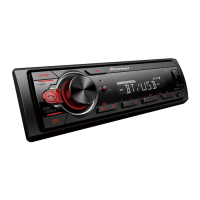
| Model | MVH-355BT |
|---|---|
| Category | Receiver |
| Brand | Pioneer |
| Type | Digital Media Receiver |
| DIN Size | 1 DIN |
| Preamp Voltage | 2V |
| Sub Preamp Output | Yes |
| Bluetooth | Yes |
| USB Port | Yes |
| USB Input | Yes |
| AUX Input | Yes |
| Auxiliary Input | Yes |
| AM/FM Tuner | Yes |
| Display Type | LCD |
| iPod/iPhone Compatibility | Yes |
| Android Compatibility | Yes |
| Steering Wheel Control Compatible | Yes |
| Power Output | 50W x 4 |
| RMS Power Output | 14W x 4 |
| RMS Power Output (CTA-2006) | 14 watts x 4 |
| Peak Output | 50W x 4 |
| Peak Output (CTA-2006) | 50W x 4 |
| Compatible Formats | MP3, WMA, FLAC |