Do you have a question about the Pioneer MVH-P8200BT and is the answer not in the manual?
Precautions for qualified service technicians regarding proper repair and safety.
Important notice regarding potential chemical exposure from the product.
Adherence to safety regulations and maintenance of a safe servicing environment.
Procedures for optimizing product performance and confirming specifications.
General precautions for servicing, including handling sensitive components and power management.
Specific guidance and recommendations for performing soldering with lead-free solder.
Detailed technical specifications covering dimensions, power, display, audio, USB, SD, tuners, and Bluetooth.
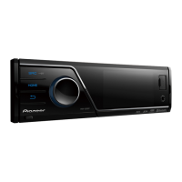
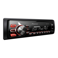
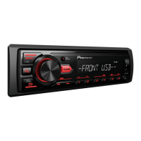
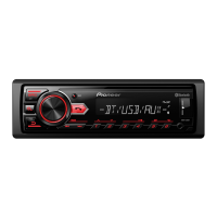
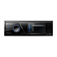
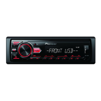
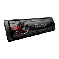
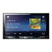
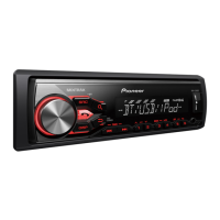
Identification and description of the head unit's physical controls and remote control functions.
Essential checks and verification steps to ensure product quality and customer satisfaction post-service.
Visual guide to the physical placement of all Printed Circuit Boards (PCBs) within the unit.
High-level functional block diagram of the Tuner Amplifier Unit.
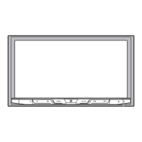
High-level functional block diagram of the Monitor PCB.
Step-by-step troubleshooting guide based on system operational states and signals.
Comprehensive list of error codes, their meanings, and troubleshooting steps.
Instructions for accessing and operating the monitor test mode for diagnostics.
Step-by-step instructions for disassembling the unit's outer casing.
Instructions for removing the Tuner Amplifier Unit from the main board.
Details on specific adjustment points and procedures for the Tuner Amp Unit.
Exploded view illustrating the contents of the product packaging.
Exploded diagrams of the unit's exterior components and their part numbers.
Detailed schematic for the Tuner Amp Unit, E.VOL Part (1/6).
Detailed schematic for the Tuner Amp Unit, SYSTEM U-COM Part (2/6).
Detailed schematic for the Tuner Amp Unit, Power Supply Part (4/6).
Visual representation of component placement and connector locations on the Tuner Amp Unit PCB.
PCB layout and connection diagram for the Monitor PCB, indicating component positions.
List of miscellaneous components like ICs, regulators, and transistors with their part numbers.
| Bluetooth | Yes |
|---|---|
| USB Port | Yes |
| Preamp Voltage | 4 volts |
| RMS Power Output | 22 watts |
| Peak Output | 50 watts |
| Detachable Face | No |
| AUX Input | Yes |
| Memory Card Slot | No |
| Radio Tuner | AM/FM |
| HD Radio | No |
| iPod Compatibility | Yes |
| Remote Control | Yes |
| Screen Size | 7 in |
| Preamp Outputs | 6-channel |
| Power Output | 50 watts |
| Compatible Formats | MP3, WMA, AAC |
| DIN Size | Double DIN |
| EQ | Yes |
| SIRIUS or XM Radio | Yes |
| EQ Settings | 13-band |
| Dimensions | 178 mm |