4.
CIRCUIT
DESCRIPTIONS
GRAPHIC
EOUALIZER
SECTION
A
graphic
equalizer is a device which divides
the
audio
frequency band into several segments
called
octaves so that the
level of each individual
octave
can be increased or
reduced.
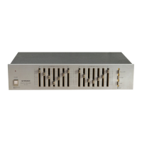
The SG-300 divides
reproduced frequencies into 7 octaves with
center
frequencies of
60
Hz,
150
Hz,
4OO
Hz,
1
kHz,
2.4kHz, 6
kHz
and 15
kHz. The level of
each
octave can be varied throughout
arange of
t10
dB,
and the left
channel and the right channel can be
adjusted independently.
Further,
when the equalizer
switch
(EQ
SW)
is
ON,
the LEDs built into the
level
controls
(sliding
variable
resistor
knobs) light
to allow the fre-
quency
response of
each
octave to
be
determined
visually. The equalizer
element is
an
LC
series
resonance
circuit in
which
the
active
element
is
an
inductor
equivalent.
This resonance
circuit is
connected to
the
variable
resistor linking the
positive
and
negative
input terminals.
(See
Figwe
4-L.',)
This
causes the
impedance
of
the resonance
circuit and
the resistance of the varirable resistor
to
act
as constants
for
the input circuit
and the
feedback
circuit.
Further,
buffer
amplifiers
are
located
before
and
after the EQ AMP
so that
the
frequency
response of
the
equalizer
element are
not
affected
by
the impedance
of audio equipment
connected to the
SG-300.
Figure
4-1 shows the
equivalent circuit for
the
graphic
equalizer
section.
In
the
area
surrounded
by
the dotted line, the
circuit on the
Q1
side
of
point
A is equivalent
to an
inductance
and a
resistance
connected in series. Any
required re-
sonant
frequency
can
be obtained by
changing the
inductance
and capacitance of
the series resonance
circuit by
varying CL, C2,
Rg
and R4.
\{ith
the
SG-300,
7
equalizer
elements $'ith
different
resonance
frequencies
are included
in one EQ
AMP,
and each frequency
segment can be
adjusted
independently.
The
frequency
response
of
each
octave is
boosted when
the slider of
the
variable
resistor
is moved toward
the
minus
input
side
(the
feedback
input side)
of EQ
AMP
ICl;
conversely,
it is reduced
when the
slider is moved
to the
plus
side.
POWER
SUPPLY
CIRCUIT
As is
shown in
Figure
4-2,
two
voltage
(+11
V
and
-
11.5 V) are
supplied
by
the
regulated
po\Mer
supply of
the
graphic
equalizer
section. The LED
set
in the knob
of each
sliding resistor
is
supplied
with
stable
cunent by
Q23,
so the
light emitted
4,
by
the
LED
is
steady.
Further,
the
load on
Q18
and
qzL
is light because
the LED
current
is
obtained after
full
wave rectification.
Q23
goes
ON
when the EQ
switch
is tumed ON to release
GND
on the
base side, and
the
LED
lights when
Q23
goes
ON.
SWITCH SECTION
o
TAPE
switch
This switch
selects
between
a
program
source or
atape
playback (or
REC
monitor) signal.
o
EO REC sritch
Turning
this
switch
on
causes an
equalized
program
source signal to
be output
to
the REC
terminals.
.
EO suritch
This switch
determines whether or not a signal is
to be equalized; when this
switch
is
OFF,
the
equalizing
circuit
is by-passed and the input
signal
is
connected
directly
to
the output ter-
minals.
L----------_____J
Fig.
4-l
Graphic equalizer
+llV
qzs
3
FOR
SLIDE
VR
KNOB
LED
5W
,{,
EQ
EQ
AMP
Fig.4-2 Power
supply
circuit