Do you have a question about the Pioneer SX-20-K and is the answer not in the manual?
Lead-free soldering guidelines and temperature settings.
Procedure for discharging components before service.
Post-repair checks for product quality and functionality.
Overall wiring diagram illustrating connections between major assemblies and components.
Diagram showing signal levels throughout the audio path from input to output.
Diagram illustrating power supply distribution and transformer connections.
Flowchart for diagnosing and resolving 'Speaker_A No sound' issues.
Troubleshooting steps for diagnosing and resolving 'Speaker_B No sound' issues.
Troubleshooting steps for diagnosing and resolving 'Phones No sound' issues.
Troubleshooting steps for diagnosing and resolving 'RECODER IN No sound' issues.
Troubleshooting steps for diagnosing and resolving 'PHONO No sound' issues.
Troubleshooting steps for diagnosing and resolving 'TUNER No sound' issues.
Troubleshooting steps for diagnosing and resolving 'FL No light' issues.
Troubleshooting steps for diagnosing and resolving 'Remote control unit does not work' issues.
Instructions for accessing and using service modes for protection detection display.
Procedure for clearing protection detection counts to factory defaults.
Details on how the unit operates and how errors are detected for DC abnormalities.
Details on how the unit operates and how errors are detected for overload conditions.
Details on how the unit operates and how errors are detected for temperature abnormalities.
Details on how the unit operates and how errors are detected for power protection.
Procedure to cancel error status and restore unit operation after DC or power protection errors.
Procedure for safely discharging electrical charge from main capacitors before disassembly.
Steps to discharge main capacitors C509 and C510 using a resistor.
Procedure to discharge the -30V supply for the FL display using a resistor.
Instructions for removing the main cabinet of the unit.
Instructions for removing the front section of the unit, including FFC disconnection.
Instructions for correctly aligning insulators during the assembly process.
Exploded view and parts list for the packing materials and accessories.
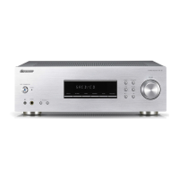
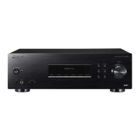
Comparison table showing differences in parts between SX-20-K/YXE8 and SX-20-S/YXE8 models.
Comparison table for exterior parts between SX-20-K/YXE8 and SX-20-S/YXE8 models.
First part of the main assembly schematic diagram detailing component connections.
PCB connection diagram for the main assembly, illustrating connector placements.
List of major assemblies and their respective part numbers.
List of semiconductor components used in the main assembly.
List of semiconductor components used in the front assembly.
| Brand | Pioneer |
|---|---|
| Model | SX-20-K |
| Category | Stereo Receiver |
| Language | English |