EasyManua.ls Logo

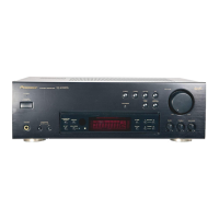
Pioneer SX-205 User Manual

Pioneer SX-205
29 pages
To Next Page IconTo Next Page
Page #1 background imageLoading...
Page #1 background image
dW)
PIONEER’
The
Art
of
Entertainment
ervice
Manual
STEREO
RECEIVER
M-255
SX-205
THIS
MANUAL
IS
APPLICABLE
TO
THE
FOLLOWING
MODEL(S)
AND
TYPE(S).
The
voltage
can
be
converted
by
Rower'Recwremeny
the
following
method.
AC120V
AC120V
AC110V/120-127V/230V/240V
With
the
voltage
selector
AC240V
CONTENTS
1.
SAFETY
INFORMATION.
...........::0cceeneeeeeeeees
2
6.
PCB
PARTS
LIST...........-ccceeceeeeeeeeaneeeeeeeeees
23
-
CHECKING
FOR
PCB
PATTERN
OF
7.
ADJUSTMENTS
.....
0...
2c
cecees
seen
neces
eerenen
sean
26
MOTHER
ASSY..........ceceecsceeceeeeeeeeesseaeeenenee
3
8.
IC
INFORMATION
............
eerie
uncDukaretiuas
aad
28
3.
EXPLODED
VIEWS,
PACKING
AND
9.
FL
INFORMATION
..........cccc
cence
eee nee
eeneee
eerie
30
PARTS
LIST...
cc
ccceseseeecseseeeceeeereeeeseeeeseees
4
10.
FOR
SX-255R/KCXJ,
YPWXJ,
SX-205/KUXJ
4,
BLOCK
DIAGRAM
...........
SeesiteT
ich
aevcs
swede!
7
AND
SDXU
uo.
ec
ee
cee
cece
eee
eee
eee
e
reece
cen
eeeeeenetes
31
5.
SCHEMATIC
AND
PCB
CONNECTION
11.
SPECIFICATIONS
.....
0...
cece
eee
ee
teen
erence
34
DIAGRAMG............ccsecesseceeteeeeeeeereeseeneeeeees
8
412.
PANEL
FACILITIES
.......
0...
ccc
eeeeeeeee
eee
neees
35
PIONEER
ELECTRONIC
CORPORATION
4-1,
Meguro
1-Chome,
Meguro-ku,
Tokyo
153,
Japan
PIONEER
ELECTRONICS
SERVICE
INC.
P.O.
Box
1760,
Long
Beach,
CA
90801-1760,
U.S.A.’
PIONEER
ELECTRONIC
[EUROPE]
N.V.
Haven
1087
Keetbergiaan
1,
9120
Meisele,
Belgium
PIONEER
ELECTRONICS
ASIACENTRE
PTE.
LTD.
501
Orchard
Road,
#10-00
Lane
Crawford
Place,
Singapore
0923
©
PIONEER
ELECTRONIC
CORPORATION
1996
O-DFG
JAN.
1996
Printed
in
Japan
Question and Answer IconNeed help?

Do you have a question about the Pioneer SX-205 and is the answer not in the manual?

Pioneer SX-205 Specifications

General IconGeneral
Frequency Response20Hz to 20kHz
Tuning RangeFM, MW
Input Sensitivity2.5mV (MM), 150mV (line)
Output150mV (line)
Speaker Load Impedance8 ohms
Channel Separation45dB (1kHz)
Signal to Noise Ratio95dB (line)
Total Harmonic Distortion0.08% (20Hz-20kHz, 8 ohms)

Summary

1. SAFETY INFORMATION

SAFETY PRECAUTIONS

General safety precautions for service technicians and customers.

PRODUCT SAFETY NOTICE

Information regarding special safety characteristics of replacement parts.

2. CHECKING FOR PCB PATTERN OF MOTHER ASSY

3. EXPLODED VIEWS, PACKING AND PARTS LIST

4. BLOCK DIAGRAM

5. SCHEMATIC AND PCB CONNECTION DIAGRAMS

5.1 OVERALL SCHEMATIC DIAGRAM

Diagram illustrating the overall schematic layout of the receiver.

Schematic Diagrams by Assembly

5.3 VOL. ASSY, FL AND UCOM ASSY AND POWER SW. ASSY (for SX-255R)

Schematics for Volume, FL/UCOM, and Power SW assemblies.

FM/AM TUNER FE MODULE Schematic

6. PCB PARTS LIST

LIST OF PCB ASSEMBLIES

List of major PCB assemblies within the unit.

MOTHER ASSY Parts

Parts list for the Mother Assembly.

COMPLEX ASSY Parts

Parts list for Complex Assemblies.

SEMICONDUCTORS

List of semiconductor components.

RELAYS

List of relay components.

COILS AND FILTERS

List of coils and filter components.

TRANSFORMER

List of transformer components.

CAPACITORS

List of capacitor components.

RESISTORS

List of resistor components.

OTHERS

List of miscellaneous components.

Additional PCB Parts Lists by Assembly

POWER SW. ASSY Parts

Parts list for the Power Switch Assembly.

SP SW. AND HP. ASSY Parts

Parts list for the Speaker Switch and Headphone Assembly.

TRANS ASSY Parts

Parts list for the Transistor Assembly.

REG ASSY Parts

Parts list for the Regulator Assembly.

PRIMARY ASSY Parts

Parts list for the Primary Assembly.

BARRIER ASSY Parts

Parts list for the Barrier Assembly.

7. ADJUSTMENTS

ADJUSTMENT OF FM TUNER SECTION

Procedures for adjusting the FM tuner section.

ADJUSTMENT OF AM (MW) TUNER SECTION

Procedures for adjusting the AM (MW) tuner section.

8. IC INFORMATION

PDG172A (IC826: FL AND UCOM ASSY) Details

Information on the PDG172A micro-computer IC.

PDG172A Pin Assignment

Diagram showing the pin layout of the PDG172A IC.

PDG172A Pin Function

Detailed description of each pin's function for the PDG172A IC.

9. FL INFORMATION

AAV7026 (V826: FL AND UCOM ASSY) Details

Information on the FL (Fluorescent Display) Tube.

FL Tube Grid Assignment

Layout of grids on the FL display.

FL Tube Anode Connection

Diagram showing anode connections for the FL display.

FL Tube Pin Assignment

Pin layout for the FL display tube.

FL Tube Pin Connection

Details of pin connections for the FL display.

10. MODEL-SPECIFIC PARTS INFORMATION

CONTRAST OF MISCELLANEOUS PARTS

Comparison of parts used across different model variations.

Model-Specific Assembly Parts Comparison (1)

FL AND UCOM Assy Parts Comparison

Parts comparison for FL and UCOM Assy across models.

VOL. Assy Parts Comparison

Parts comparison for the Volume Assy across models.

Model-Specific Assembly Parts Comparison (2)

MOTHER Assy Parts Comparison

Parts comparison for the Mother Assy across models.

POWER SW. Assy Parts Comparison

Parts comparison for the Power SW. Assy across models.

11. SPECIFICATIONS

Amplifier Section Specifications

Technical specifications for the amplifier section.

AM Tuner Section Specifications

Technical specifications for the AM tuner section.

FM Tuner Section Specifications

Technical specifications for the FM tuner section.

Miscellaneous Specifications

General specs: power, dimensions, furnished parts.

12. PANEL FACILITIES

Antenna and Audio Jacks

Description of antenna and audio input/output jacks.

Control and Speaker Terminals

Description of control, speaker, and voltage selector terminals.

AC OUTLET and Cautions

Description of the AC OUTLET and associated cautions.

Front Panel Controls Overview

Power Controls and Indicators

Description of Power STANDBY/ON switch and indicator.

Source Selection and Playback Controls

Buttons for source selection, tape monitoring, volume, and headphones.

Speaker Selection and Memory

Buttons for speaker selection and memory functions.

Front Panel Buttons and Indicators

Tuning and Mode Selection Buttons

Buttons for FM mode selection, tuning, and station class.

Tone, Balance, and Display

Controls for bass, treble, balance, and display indicators.

Related product manuals