3
2. Installation accessory
Precaution of installing the wire controller
1. This manual provides the installation method of wired
controller. Please refer to the wiring diagram of this installation
manual to connect the wire controller with indoor unit.
2. The wired controller works in low voltage loop circuit. Forbid
to directly contact the cable of high voltage above,like 115V,
220V,380V, and don’t wire this kind of wire in the
said loop; wiring clearance between congured tubes should
be at the range of 300~500mm or above.
3. The Shielded wire of the wired controller must be grounded
rmly.
4. Upon nish the wire controller connection, do not employed
tramegger to detect the insulation.
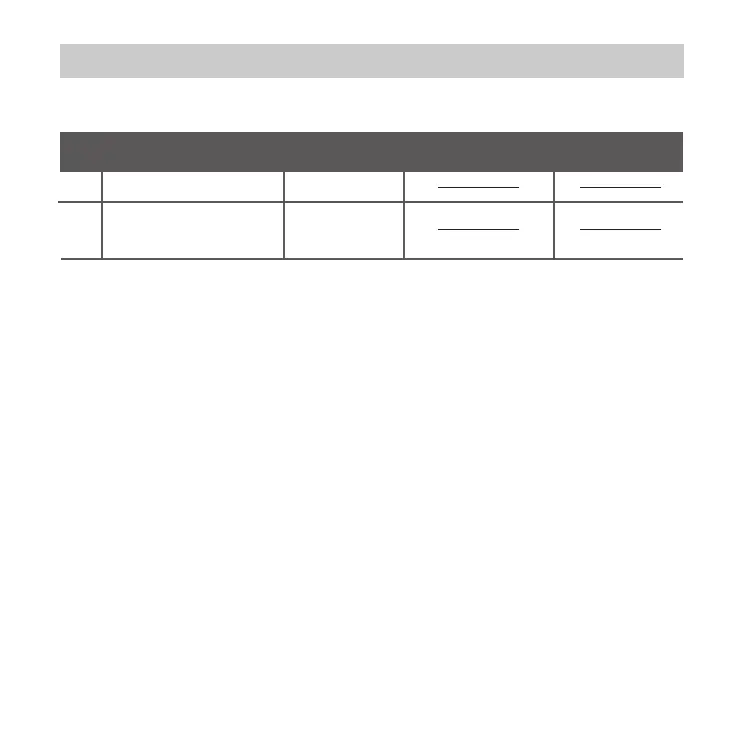
2. Prepare the following assemblies on the site.
1
2
1
Switch box
Wiring Tube(Insulating
Sleeve and Tightening
Screw)
Qty.(embeded
into wall)
No.
Name
Remarks
Specification
(only for reference)
1
 Loading...