Do you have a question about the Pioneer VSA-AX10i-S and is the answer not in the manual?
Table listing part number variations between models VSX-49TXi/KU/CA and VSA-AX10i-S/HY.
Diagrams illustrating the assembly of the remote control unit.
List of parts related to the packaging and accessories of the unit.
Comparison of part numbers for the A/V I/O assembly between models.
Comparison of part numbers for the Composite assembly between models.
Comparison of part numbers for the V-Convert assembly between models.
Comparison of part numbers for the Component assembly between models.
Comparison of part numbers for the Analog In & A/D assembly between models.
Comparison of part numbers for the Display assembly between models.
Comparison of part numbers for the AC Primary assembly between models.
Comparison of part numbers for the Mother assembly between models.
Comparison of part numbers for the SP (B) assembly between models.
Comparison of part numbers for the SP (A) assembly between models.
Comparison of part numbers for the Posister (L) assembly between models.
Comparison of part numbers for the Posister (R) assembly between models.
Diagram showing the connection points for the Posister (MT) assembly.
Table comparing miscellaneous parts between AXD7295 and AXD7296 remote controls.
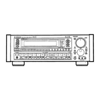
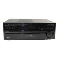
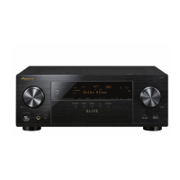
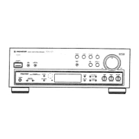
This document serves as a comprehensive service manual for the Pioneer VSA-AX10i-S Audio/Video Multi-Channel Receiver, a sophisticated piece of audio equipment designed to deliver an immersive sound and vision experience. The manual outlines various aspects of the device, from its overall structure and components to detailed wiring diagrams and maintenance procedures, ensuring that technicians and users can effectively understand, operate, and service the unit.
The Pioneer VSA-AX10i-S is an advanced audio/video multi-channel receiver, serving as the central hub for a home entertainment system. Its primary function is to receive, process, and amplify audio and video signals from multiple sources, delivering high-quality sound through a multi-speaker setup and routing video signals to a display. This receiver is designed to handle a wide array of audio and video inputs, making it versatile for various entertainment needs, including movies, music, and gaming.
The receiver integrates several key functional blocks to achieve its performance. The Audio/Video I/O (Input/Output) Assy manages the routing of both analog and digital audio and video signals, ensuring seamless switching between different sources such as DVD/LD, TV/HDTV, SAT, VCRs, and dedicated audio inputs like PHONO, CD, TUNER, and MULTI CH INPUT. This section is crucial for selecting the desired source and directing its signals to the appropriate processing stages.
The A/D & Control Assy plays a vital role in converting analog audio signals to digital for processing, and vice versa. It also houses the control logic that governs the overall operation of the receiver, including user interface interactions and system management. The Display Assy provides visual feedback to the user, showing selected inputs, volume levels, and various operational parameters, enhancing user interaction and control.
For video processing, the V-Convert Assy is responsible for converting video signals between different formats or standards, ensuring compatibility with various display devices. The Composite Assy handles composite video signals, a common format for many older video sources, and integrates a video function selector to manage these signals. The Component Assy likely deals with component video signals, which offer higher quality than composite.
The audio amplification is managed by the SP (A) Assy and SP (B) Assy, which are dedicated to driving the speaker outputs. These sections contain the power amplification circuitry necessary to deliver robust and clear audio to multiple channels, supporting a multi-channel surround sound experience. The Posister (L) Assy, Posister (R) Assy, and Posister (MT) Assy are likely involved in protecting the speaker outputs or other sensitive components from overcurrent or overheating, ensuring the longevity and reliability of the amplifier sections.
The AC Primary Assy and Power SW Assy handle the main power input and distribution within the receiver. They ensure that stable and appropriate power is supplied to all internal circuits, including the Power Transformer (T1), which steps down the incoming AC voltage to the various levels required by the receiver's components. The Fuse Assy provides critical overcurrent protection for the entire unit, safeguarding against electrical faults.
The DSP Diode Assy and Diode Assy are essential for rectifying AC power into DC power for the various electronic components, contributing to the stability and efficiency of the power supply. The TRANS (A) Assy and TRANS (B) Assy likely refer to additional transformer or power regulation stages that provide specific voltage levels to different parts of the circuit.
The Mother Assy serves as the main circuit board, integrating many of these functional blocks and providing the central communication pathways between them. It houses the core processing units and control circuitry that orchestrate the receiver's complex operations.
The Pioneer VSA-AX10i-S is designed for intuitive use, offering a range of features that enhance the user experience in a home entertainment setup. The Front Panel Section provides direct access to essential controls, including rotary knobs for volume and other adjustments, and buttons for power and various functions. The Display Assy on the front panel offers clear visual feedback, allowing users to easily monitor the receiver's status and settings.
The Remote Control Unit is a primary interface for interacting with the receiver from a distance. It allows users to switch between different audio and video sources, adjust volume, select sound modes, and control other advanced features without needing to be near the unit. The remote control's design, including key tops and rubber sheets, is optimized for comfortable and reliable operation.
The receiver supports a variety of input sources, indicated by the detailed A/V I/O Assy and Analog In & A/D Assy. Users can connect multiple devices such as DVD players, televisions, satellite receivers, VCRs, turntables (PHONO), CD players, and other multi-channel audio sources. This extensive connectivity ensures that the receiver can accommodate a diverse range of modern and legacy entertainment equipment.
The Speaker Relay and associated circuitry in the SP (A) Assy and SP (B) Assy manage the connection to multiple speaker channels, enabling a surround sound configuration. This allows users to enjoy movies and music with a rich, multi-dimensional audio experience.
The Input Selector Assy and A/V MR Function Selector facilitate easy switching between different audio and video inputs, ensuring that the correct signals are routed to the processing stages and ultimately to the display and speakers. This streamlined selection process simplifies the user's interaction with their entertainment system.
The service manual for the Pioneer VSA-AX10i-S provides detailed information crucial for the maintenance and repair of the device, ensuring its long-term reliability and performance.
A key maintenance feature is the Line Voltage Selection capability. The manual explicitly describes how to modify the wiring of the power-supply block at the primary winding of the power transformer to convert the operating voltage from 220-230V to 240V. This involves disconnecting the AC power cord, removing the cover, changing specific connection wires on the SP (B) ASSY, and applying a new line voltage label on the rear panel. This feature is vital for adapting the receiver to different regional power standards, ensuring safe and correct operation.
The manual includes a Contrast of Miscellaneous Parts section, which highlights differences in components between the VSA-AX10i-S/HY model and the base model (VSX-49TXi/KU/CA). This information is critical for identifying the correct replacement parts during servicing. Parts marked with "NSP" (Not in our Master Spare Parts List) indicate components that are generally unavailable, guiding technicians to consider alternative solutions or specialized sourcing if necessary.
For safety, the manual emphasizes that components marked with a specific symbol (a triangle with an exclamation mark) indicate parts with importance for the safety factor. When replacing these parts, it is crucial to use parts of identical designation to maintain the device's safety standards. Similarly, screws adjacent to a specific mark are used for disassembly, providing clear guidance for technicians.
The PCB Parts List and Schematic Diagram sections are invaluable for troubleshooting and repair. They provide a comprehensive breakdown of all components on each printed circuit board (PCB), along with their part numbers and descriptions. The schematic diagrams illustrate the electrical connections and signal paths within the receiver, enabling technicians to trace circuits, diagnose faults, and verify component functionality. The diagrams also highlight power supply routes, which are essential for diagnosing power-related issues.
The Exploded Views section, particularly the Packing Section, provides a visual guide to the physical assembly of the receiver and its accessories. While primarily for packing, it can also assist in understanding the overall structure and how various external components fit together, which is useful during reassembly after repairs.
Specific notes within the manual provide general guidelines for resistors, capacitors, and diodes, including units, rated power, tolerance, and voltage ratings. This detailed component information is essential for selecting appropriate replacement parts and understanding their electrical characteristics. The manual also specifies that "No marked Diodes are 1SS355," providing a default assumption for unmarked diodes, which simplifies parts identification.
The inclusion of PCB Connection Diagrams for various assemblies, such as the POSISTER (MT) ASSY, further aids in maintenance by illustrating how different PCBs connect to each other. This helps technicians understand the overall system architecture and identify connection points for testing or replacement.
Finally, a critical Note for Fuse Replacement explicitly states: "CAUTION—FOR CONTINUED PROTECTION AGAINST RISK OF FIRE. REPLACE WITH SAME TYPE AND RATINGS ONLY." This warning underscores the importance of using correct fuses to prevent fire hazards and ensure the continued safe operation of the receiver. This emphasis on safety and precise component replacement is a cornerstone of the maintenance guidelines provided in the manual.
| continuous power output (stereo mode) | 170 W + 170 W (DIN 1 kHz, THD 1 %, 6 Ω) |
|---|---|
| continuous power output (surround mode) | Front: 170 W + 170 W, Center: 170 W, Surround: 170 W + 170 W, Surr. back: 170 W + 170 W (DIN 1 kHz, THD 1 %, 6 Ω) |
| rated power output | 150 W + 150 W (20 Hz-20 kHz, THD 0.09 %, 6 Ω) |
| input sensitivity/impedance (PHONO MM) | 4.7 mV/47 kΩ |
|---|---|
| input sensitivity/impedance (LINE) | 382 mV/47 kΩ |
| phono overload level | 120 mV (T.H.D. 0.1 %, 1kHz) |
| power requirements | AC 220 - 230 V, 50/60 Hz |
|---|---|
| power consumption | 660 W |
| power consumption in standby mode | 0.65 W |
| dimensions | 440 (W) × 203 (H) × 476 (D) mm |
| weight (without package) | 29.8 kg |