EasyManua.ls Logo

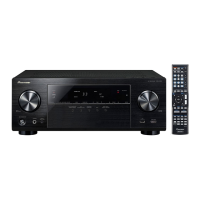
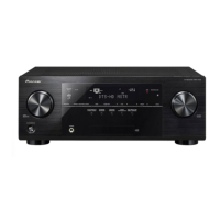
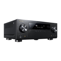
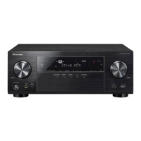
Pioneer VSX-1022-K User Manual

Pioneer VSX-1022-K
161 pages
To Next Page IconTo Next Page
Page #1 background imageLoading...
Page #1 background image
ORDER NO.
PIONEER CORPORATION 1-1, Shin-ogura, Saiwai-ku, Kawasaki-shi, Kanagawa 212-0031, Japan
PIONEER ELECTRONICS (USA) INC. P.O. Box 1760, Long Beach, CA 90801-1760, U.S.A.
PIONEER EUROPE NV Haven 1087, Keetberglaan 1, 9120 Melsele, Belgium
PIONEER ELECTRONICS ASIACENTRE PTE. LTD. 253 Alexandra Road, #04-01, Singapore 159936
PIONEER CORPORATION
2012
2012 Printed in Japan
VSX-1022-K
RRV4306
AV Receiver
VSX-1022-K
VSX-42
VSX-822-K
THIS MANUAL IS APPLICABLE TO THE FOLLOWING MODEL(S) AND TYPE(S).
Model Type Power Requirement Remarks
VSX-1022-K CUXESM AC 120 V
VSX-42 UXECB AC 120 V
VSX-822-K CUXESM AC 120 V
K-MZV MAR.

Table of Contents

Question and Answer IconNeed help?

Do you have a question about the Pioneer VSX-1022-K and is the answer not in the manual?

Pioneer VSX-1022-K Specifications

General IconGeneral
BrandPioneer
ModelVSX-1022-K
CategoryStereo Receiver
LanguageEnglish

Summary

Safety Information

Service Precautions

Specifications

Model Specifications

Technical specifications for VSX-1022-K, VSX-822-K, and VSX-42 models.

Block Diagrams

4.2 Audio Block Diagram

Block diagrams illustrating the audio signal flow for different models.

4.4 D-Main Block Diagram

Block diagrams detailing the D-Main assembly's signal processing.

Diagnosis and Troubleshooting

5.1 Troubleshooting

Step-by-step guide for common issues and fault diagnosis.

HDMI Troubleshooting

Simple diagnosis steps for HDMI connection issues like no display or sound.

Service Mode

Setting and Adjustment

8.1 Adjustment Required When the Unit is Repaired or Replaced

Adjustments needed after replacing specific assemblies or parts.

Firmware Update

(1) MAIN microcomputer firmware update

Procedure for updating the firmware of the main microcomputer.

(2) SUB microcomputer firmware update

Procedure for updating the SUB microcomputer firmware via Network Function.

Idle Current Adjustment

Schematic Diagram

10.1 AUDIO ASSY

Schematic diagram for the Audio Assembly, detailing its internal circuitry.

10.6 MAIN ASSY

Schematic diagram for the Main Assembly, showing power supply and speaker connections.

10.7 D-MAIN ASSY (1/7)(VSX-1022-K, VSX-42)

First part of the schematic for the D-MAIN Assembly.

10.21 CPU ASSY

Schematic diagram for the CPU Assembly, detailing its pin functions.

PCB Connection Diagram

Related product manuals