Do you have a question about the Pioneer VSX-456 and is the answer not in the manual?
| Channels | 5.1 |
|---|---|
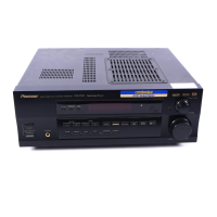
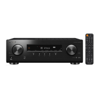
| Type | AV Receiver |
| Power Output (per channel) | 100 W |
| Total Harmonic Distortion (THD) | 0.08% |
| Input Sensitivity | 200 mV |
| Input Impedance | 47 kΩ |
| Signal-to-Noise Ratio | 98 dB |
| Tuner Type | AM/FM |
| Preset Stations | 30 |
| Frequency Response | 5 Hz - 100 kHz (+0 dB, -3 dB) |
| Speaker Impedance | 6-16 Ohms |
Safety precautions for customer and technician, including leakage current checks.
Notice about special safety characteristics of parts and potential hazards.
Information regarding product packing and components.
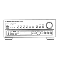
Diagram showing external components and their assembly.
Diagram showing interconnections between major circuit boards.
Schematic for the input assembly.
Schematics for input, trans, and MOS FET assemblies.
Schematics for input, front input, and regulator assemblies.
Schematic for the Pro Logic assembly.
Schematic for the volume assembly.
Schematic for the R/C speaker assembly.
Schematic for the R/C amplifier assembly.
Schematics for Video SR and Primary assemblies.
Schematic for the FM/AM tuner module.
PCB connection diagrams for R/C speaker and MOS FET assemblies.
PCB connection diagrams for power switch and front input assemblies.
PCB connection diagram for the FL/U-COM assembly.
PCB connection diagrams for Trans, Reg.1, and Primary assemblies.
PCB connection diagram for the volume assembly.
PCB connection diagram for the R/C amplifier assembly.
PCB connection diagrams for the Pro Logic assembly.
PCB connection diagram for the FM/AM tuner module.
PCB connection diagrams for the Video/SR assembly.
Adjustment procedures for FM and AM tuner sections.
Information on general parts and IC component details.
Details of the FL display and its pin assignments.
Block diagram illustrating the unit's functional sections and interconnections.
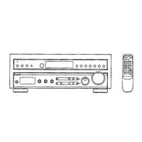
Exploded view and parts list for the remote control unit.
Schematic and PCB diagrams for the remote control unit.
Parts list for the remote control unit's PCB.
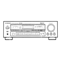
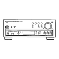
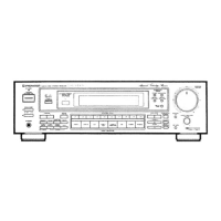
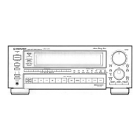
Overview of front panel indicators and controls for both models.
Detailed explanation of the VSX-D506S front panel controls and indicators.
Detailed explanation of the VSX-456 front panel controls and indicators.