Do you have a question about the Pioneer VSX-50 and is the answer not in the manual?
Precautions for customer and service technician safety.
Importance of using specified replacement components for safety.
Conform to regulations and follow safety instructions during servicing.
Importance of adjustments for maintaining product performance.
Proper cleaning to restore performance of specific parts.
Overall block diagram of the audio section.
Overall wiring diagram of the system.
Exploded view of the external parts of the unit.
Exploded view of the internal parts of the unit.
PCB connection diagram for FM/AM TUNER MODULE.
Adjustment procedures for the tuner section.
Diagnostic procedures for troubleshooting.
List of parts used in the unit.
Instructions for cleaning the unit.
List of integrated circuits.
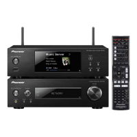
Information about the display unit.
Description of the front panel controls and indicators.
Description of speaker output terminals.
Details on connecting antennas.
Description of digital audio input connections.
Description of analog audio/video connections.
| Brand | Pioneer |
|---|---|
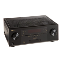
| Model | VSX-50 |
| Category | Media Player |
| Language | English |