Do you have a question about the Pioneer VSX-521-K and is the answer not in the manual?
General safety guidelines for service technicians, including leakage current checks.
Information on safety-related characteristics of components and the importance of using specified parts.
Conforming to regulations, using specified parts, and maintaining a safe servicing environment.
Procedures for optimum adjustments and confirmation of product characteristics.
Guidelines for using specified lubricants and adhesives for repairs.
Procedures for cleaning parts to restore performance, such as optical pickups.
Steps to protect products from damage during transit, including setting shipping modes.
Guidance on using lead-free solder and appropriate soldering iron temperatures for repairs.
Notices regarding discharging and ground points connection for servicing safety.
Technical details of the amplifier's power output, impedance, and audio specifications.
Specifications for HDMI, USB, and other digital input/output terminals.
Input sensitivity, output level, and signal-to-noise ratio for the audio circuits.
Signal levels and resolutions for composite and component video inputs.
Frequency ranges and antenna inputs for AM and FM tuners.
List of included accessories such as remote control, microphone, and cables.
Essential checks to perform after servicing to ensure product quality and functionality.
List of special jigs required for diagnosis and firmware updates.
Specific lubricants and glues used in the product and their part numbers.
Visual identification of PCB locations within the VSX-821-K and VSX-921-K models.
A comprehensive block diagram showing the overall wiring connections between major assemblies.
Detailed block diagram of the audio circuits for VSX-821-K and VSX-521-K models.
Detailed block diagram of the audio circuits specifically for the VSX-921-K model.
Block diagram for the D-MAIN assembly, detailing its functions for VSX-821-K/521-K.
Block diagram for the D-MAIN assembly, detailing its functions for VSX-921-K.
Step-by-step troubleshooting procedures for common issues encountered with the unit.
Diagnosing issues with HDMI authentication and connectivity between source and display.
Basic checks for no display or sound from the monitor via HDMI.
Initial checks to perform before troubleshooting iPod connectivity issues.
Verifying power supply voltages for iPod connectivity troubleshooting.
Initial checks to perform before troubleshooting Bluetooth connectivity.
Checking the Bluetooth detection circuit and voltage levels.
Verifying power supply voltages for Bluetooth module troubleshooting.
Checking the voltage for Bluetooth identification signals.
Verifying communication signals between Bluetooth module and main unit.
Testing audio output signals from the Bluetooth module.
Schematic of the overload and DC protection circuits within the unit.
Accessing and using the service mode to display protection detection counts.
Unit behavior and indications upon detecting a DC error in the amplifier.
Unit behavior and indications upon detecting an overload or overcurrent error.
Procedures for safely discharging capacitors before disassembly.
Step-by-step guide to removing the front panel section of the unit.
Instructions for removing the chassis back and D-MAIN Assy.
Steps for removing the main assembly, including related parts like wire guides.
Guidelines on when to perform adjustments after replacing assemblies or parts.
Details on how the unit is packed, including a parts list for packing materials.
| Impedance | 8 Ω |
|---|---|
| Receiver type | - |
| Frequency range | 20 - 20000 Hz |
| RMS rated power | 550 W |
| Audio output channels | 5.1 channels |
| Signal-to-Noise Ratio (SNR) | 79 dB |
| Total Harmonic Distortion (THD) | 0.05 % |
| Power output per channel (1KHz@6 Ohm) | 125 W |
| Power output per channel (20-20KHz@8 Ohm) | - W |
| AirPlay | No |
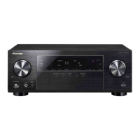
| Product color | Black |
| Audio decoders | Dolby Digital EX, Dolby Digital Plus, Dolby Pro Logic IIz, Dolby TrueHD, DTS-HD |
| Apple docking compatibility | Not supported |
| HDMI in | 4 |
| Digital audio coaxial in | 1 |
| Digital audio optical in | 2 |
| Multichannel audio input type | Terminals |
| Headphone connectivity | 3.5 mm |
| Connectivity technology | Wired |
| AM band range | 530 - 1700 kHz |
| FM band range | 87.5 - 108 MHz |
| Supported radio bands | AM, FM |
| Preset stations quantity | 30 |
| AC input voltage | 120 V |
| AC input frequency | 60 Hz |
| Power consumption (standby) | 0.4 W |
| Power consumption (typical) | 415 W |
| Depth | 363 mm |
|---|---|
| Width | 435 mm |
| Height | 168 mm |
| Weight | 9000 g |





 Loading...