EasyManua.ls Logo

Pioneer VSX-607RDS User Manual

Pioneer VSX-607RDS
58 pages
To Next Page IconTo Next Page
Page #1 background imageLoading...
Page #1 background image
ORDER NO.
RRV1953
T - IZK MAY 1998 Printed in Japan
PIONEER ELECTRONIC CORPORATION 4-1, Meguro 1-Chome, Meguro-ku, Tokyo 153-8654, Japan
PIONEER ELECTRONICS SERVICE, INC. P.O. Box 1760, Long Beach, CA 90801-1760, U.S.A.
PIONEER ELECTRONIC (EUROPE) N.V. Haven 1087, Keetberglaan 1, 9120 Melsele, Belgium
PIONEER ELECTRONICS ASIACENTRE PTE. LTD. 501 Orchard Road, #10-00 Wheelock Place, Singapore 238880
PIONEER ELECTRONIC CORPORATION 1998
c
VSX-607RDS
AUDIO/VIDEO MULTI-CHANNEL RECEIVER
VSX-407RDS
THIS MANUAL IS APPLICABLE TO THE FOLLOWING MODEL(S) AND TYPE(S).
The voltage can be converted by the
following method.
The illustration shows the VSX-607RDS.
Type
Model
Power Requirement
VSX-607RDS VSX-407RDS
HYXKEW AC220-230V AC240V,
HYXKGR AC220-230V AC240V,
: Alter the wiring of the Power-supply block at the primary winding of Power-transformer referring to the "Line Voltage Selection"
described in Service Manual.
1. SAFETY INFORMATION ...................................... 2
2. EXPLODED VIEWS AND PARTS LIST ................ 3
3. SCHEMATIC DIAGRAM ....................................... 8
4. PCB CONNECTION DIAGRAM .......................... 24
5. PCB PARTS LIST ............................................... 31
6. ADJUSTMENT .................................................... 35
CONTENTS
7. GENERAL INFORMATION ................................ 36
7.1 PARTS ......................................................... 36
7.1.1 IC .......................................................... 36
7.1.2 DISPLAY............................................... 42
7.2 DISASSEMBLY ........................................... 43
7.3 DIAGNOSIS ................................................. 45
7.4 BLOCK DIAGRAM....................................... 46
7.5 REMOTE CONTROL UNIT
[CU-VSX131 (AXD7169)] ............................ 48
8. PANEL FACILITIES AND SPECIFICATIONS .. 52
Question and Answer IconNeed help?

Do you have a question about the Pioneer VSX-607RDS and is the answer not in the manual?

Pioneer VSX-607RDS Specifications

General IconGeneral
BrandPioneer
ModelVSX-607RDS
CategoryReceiver
LanguageEnglish

Summary

SAFETY INFORMATION

SAFETY PRECAUTIONS

Precautions for technician and customer safety, including leakage current check.

PRODUCT SAFETY NOTICE

Importance of using specific replacement parts for safety.

EXPLODED VIEWS AND PARTS LIST

PACKING

Exploded view and parts list for packing components.

EXTERIOR SECTION

Exploded view of exterior parts and their list.

FRONT PANEL SECTION

Exploded view of the front panel parts and their list.

SCHEMATIC DIAGRAM

OVERALL CONNECTION DIAGRAM

High-level connection diagram showing main assemblies and their interconnections.

MOTHER ASSY (1/3)

Schematic diagram for the Mother Assembly, Part 1 of 3.

MOTHER ASSY (2/3)

Schematic diagram for the Mother Assembly, Part 2 of 3.

MOTHER (3/3), CONNECTION AND TRANS 2 ASSEMBLIES

Schematic diagrams for Mother (Part 3), Connection, and Trans 2 assemblies.

FRONT ASSY

Schematic diagram for the Front Assembly.

VOLUME DSP ASSY (1/2)

Schematic diagram for the Volume DSP Assembly, Part 1 of 2.

VOLUME DSP ASSY (2/2)

Schematic diagram for the Volume DSP Assembly, Part 2 of 2.

FRONT SPEAKER, HEADPHONE, FRONT INPUT, TRANS 1, POWER SW AND PRIMARY ASSEMBLIES

Schematic diagrams for Front Speaker, Headphone, Front Input, Trans 1, Power SW, and Primary Assemblies.

PCB CONNECTION DIAGRAM

MOTHER ASSY

PCB connection diagram for the Mother Assembly.

CONNECTION, TRANS 2 AND FRONT ASSEMBLIES

PCB connection diagrams for Connection, Trans 2, and Front Assemblies.

VOLUME DSP ASSY

PCB connection diagram for the Volume DSP Assembly.

FRONT SPEAKER, HEADPHONE AND FRONT INPUT ASSEMBLIES

PCB connection diagrams for Front Speaker, Headphone, and Front Input Assemblies.

TRANS 1, POWER SW AND PRIMARY ASSEMBLIES

PCB connection diagrams for Trans 1, Power SW, and Primary Assemblies.

PCB PARTS LIST

LIST OF WHOLE PCB ASSEMBLIES

Comprehensive list of all PCB assemblies and their part numbers.

CONTRAST TABLE

Table detailing differences in parts for various model configurations.

GENERAL INFORMATION

PARTS

Information on specific parts, including ICs and their diagrams.

DISASSEMBLY

Step-by-step procedures for disassembling major unit components.

DIAGNOSIS

Procedure for diagnosing power amplifier ICs on the Mother board.

BLOCK DIAGRAM

Block diagram illustrating the overall system architecture and signal flow.

REMOTE CONTROL UNIT

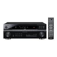
Exploded views, parts list, schematic, PCB diagrams and parts list for the remote.

PANEL FACILITIES AND SPECIFICATIONS

PANEL FACILITIES

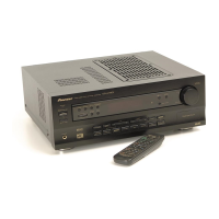
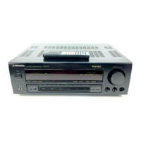
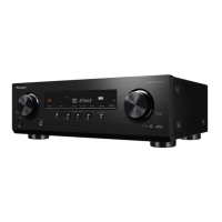
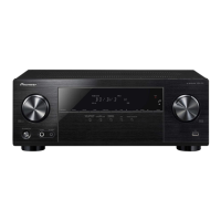
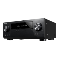
Detailed description of the front panel controls and functions.

Display

Explanation of the unit's display indicators and their meanings.

Connecting Devices

DVD 5.1-Channel Input Terminals

Instructions for connecting DVD players with 5.1-channel output.

SPECIFICATIONS

Related product manuals