Do you have a question about the Pioneer VSX-74TXVi and is the answer not in the manual?
The following check should be performed for the continued protection of the customer and service technician.
Many electrical and mechanical parts in the appliance have special safety related characteristics.
Please conform to product regulations (such as safety and radiation regulations), and maintain a safe servicing environment.
Use grease and adhesives that are equal to the specified substance. Make sure the proper amount is applied.
For parts that require cleaning, such as optical pickups, tape deck heads, lenses and mirrors used in projection monitors, proper cleaning should be performed.
Specifications for the amplifier section, including continuous power output and total harmonic distortion.
Specifications for the audio section, including input sensitivity, frequency response, and signal-to-noise ratio.
Specifications for the FM tuner section, including frequency range, usable sensitivity, and signal-to-noise ratio.
Parts marked by "NSP" are generally unavailable because they are not in our Master Spare Parts List.
Diagram showing the exterior components of the unit and their part numbers.
Exploded view of the chassis section, showing internal component layout and connections.
Diagram illustrating the overall functional blocks and signal flow within the receiver.
Diagram showing the overall wiring connections between different assemblies in the unit.
PCB layout diagram for the Preout & Control Assembly.
PCB layout diagram for the Audio & Multi Channel Input Assembly.
Describes how to diagnose a defective part in the DSP Assy, including simplified diagnosis and troubleshooting steps.
Flowchart to determine the nature of the HDMI problem: no sound, no picture, or abnormal picture.
Troubleshooting steps when audio is missing but video is present via HDMI.
Information on symptoms and remedies for i.LINK interface issues, including connection checks and database reset.
Describes common error codes displayed on the unit when using an iPod and their causes/measures.
Step-by-step procedure to check the XM RADIO function, including antenna and signal checks.
Procedure for safely discharging capacitors in the Power Amp Block before removal.
Procedure for checking the power transistor and collector resistance of each channel using a tester.
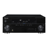
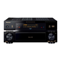
Illustration showing the front panel of the VSX-74TXVi with numbered controls and their functions.
Lights indicating the currently selected input signal; AUTO lights for automatic selection.
Shows the overall volume level, from -80dB (minimum) to +12dB (maximum).
Switches the remote to control the receiver; use SHIFT for other component controls.
Controls for tuner, component, and system setup accessed via RECEIVER and SHIFT buttons.
Connectors for high-quality audio/video connection to compatible HDMI devices.
Inputs for connecting video sources with component video output.