Do you have a question about the Pioneer VSX-817-K and is the answer not in the manual?
Checks to be performed for continued protection of customer and service technician.
Measure leakage current to earth ground and check for safety.
Notice regarding special safety characteristics of electrical and mechanical parts.
Conform to regulations and maintain a safe servicing environment.
High-level block diagram showing the main functional units and signal flow.
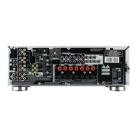
Diagram showing the interconnections between major internal assemblies.
Schematic diagrams for Power Pack, Trans2, and Trans3 assemblies.
Schematic diagrams for Component Video, Head Phone, and 5.1CH Input assemblies.
Schematic diagrams for Front Display, Rotary Encoder, and Power Key assemblies.
Schematic diagrams for S.Video, Trans4, and Regulator assemblies.
Schematic diagrams for Component Video and Board to Board assemblies.
Schematic diagrams for Video, Digital Input, Front Video, Primary, and Trans1 assemblies.
Diagrams showing PCB layouts and component placement.
Schematic diagrams for Component Video and Board to Board assemblies.
PCB layout diagrams for Digital Input and Front Video Assys (Side A and Side B).
General diagnostic steps and component identification for disassembly.
Troubleshooting flowchart for Codec analog output on various channels.
Block diagram of the DSP Assy, showing connections to other modules.
Simple diagnosis and troubleshooting for HDMI no picture or sound issues.
Basic troubleshooting steps for HDMI connection issues.
Troubleshooting steps for display or sound problems related to HDMI.
Troubleshooting steps for XM/DT, DSP output, and Codec output signals.
Check points for the HDMI & DVC Assy, showing common and video converter sections.
Block diagram illustrating the HDMI and DVC signal paths and components.
General diagnostic steps and component identification for disassembly.
Detailed explanation of detection circuits, amplifier protection, and failure diagnosis.
Diagrams illustrating DC detection, overload detection, and fan stop protection circuits.
Diagram illustrating the DC detection circuit for the power amplifier.
Diagram illustrating the overload detection circuit for the front channel.
Diagram illustrating the fan stop protection circuit.
Circuit diagram showing XPROTECT detection for various voltage supplies.
Operation specifications for DC abnormality, overload, and fan stop protection.
Operation specification for DC abnormality detection and its recovery.
Operation specification for overload detection and its recovery.
Operation specification for XPROTECT detection, including behavior when detected.
Flowchart for detecting fan stop and its recovery procedure.
Flowchart to diagnose amplifier failures, including checks for fuses, voltages, and components.
Flowchart to diagnose amplifier failures, including checks for fuses, voltages, and components.
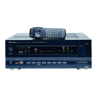
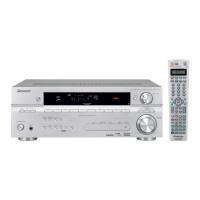
Explanation of remote control buttons for receiver and component operation.
| Impedance | 8 Ω |
|---|---|
| Audio output channels | 7.1 channels |
| Signal-to-Noise Ratio (SNR) | 88 dB |
| Output power | 110 W |
| Frequency band | 0.005 — 100 GHz |
| Dimensions (WxDxH) | 420 x 352.5 x 158 mm |
| Power requirements | 220 — 230 V, 50/60 Hz |
| Connectivity technology | Wired |
| Headphone outputs | 1 |
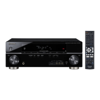
| Product color | Black |
| Power consumption (standby) | 0.5 W |
| Power consumption (typical) | 360 W |
| Weight | 8500 g |
|---|