EasyManua.ls Logo

Pioneer VSX-9500S Service Manual

Pioneer VSX-9500S
62 pages
To Next Page IconTo Next Page
Page #1 background imageLoading...
Page #1 background image
Q
PIONEER’
The
future
of
sound
and
vision.
PSYst4
4
(ee
PAL
EYED
ORDER
NO.
ARP1838
AUDIO/VIDEO
STEREO
RECEIVER
VSX=9500S
VSX-7500S
VSX-9500S
AND
VSX-7500S
HAVE
FOLLOWING
VERSIONS:
AC120V
only
Export
destination
U.S.A.and
Canada
AC110V,120V-~127V,220V,240V
KUC
SD/G
(switchable)
¢
This
manual
is
applicable
to
the
VSX-9500S/KUC,
SD/G,
VSX-7500S/KUC
and
SD/G
types.
©
For
the
VSX-9500S/SD/G,
VSX-7500S/KUC
and
SD/G
types,
refer
to
page
74—77.
CONTENTS
1,
SAFETY
INFORMATION
2.
EXPLODED
VIEWS
AND
PARTS
LIST
3.
SCHEMATIC
DIAGRAMS
AND
P.C.BOARDS
CONNECTION
DIAGRAMS
ae
4,
ELECTRICAL
PARTS
LIST
-
5.
ADJUSTMENTS
6.
REMOTE
CONTROL
UNIT
(AXD1100)
--
69
7.
FOR
VSX-9500S/SD/G,
VSX-
7500/KUC
AND
SD/G
TYPES
8.
PANEL
FACILITIES
9.
SPECIFICATIONS--
PIONEER
ELECTRONIC
CORPORATION
4-1,
Meguro
1-Chome,
Meguro-ku,
Tokyo
153,
Japan
PIONEER
ELECTRONICS
SERVICE
INC.
P.O.
Box
1760,
Long
Beach,
California
90801
U.S.A.
PIONEER
ELECTRONICS
OF
CANADA,
INC.
505
Cochrane
Drive;
Markham,
Ontario
LR
8E3
Canada
PIONEER
ELECTRONIC
[EUROPE]
N.V.
Keetbergiaan
1,
2740
Beveren,
Belgium
ELECTRONICS
AUSTRALIA
PTY.
LTD.
178-184
Boundaty
Road,
Braeside,
Victoria
3195,
Australia
TEL:
[03]
580-9911
PIONEER
©
PIONEER
ELECTRONIC
CORPORATION
1989
YA
JUNE
1989
Printed
in
Japan.

Other manuals for Pioneer VSX-9500S

Question and Answer IconNeed help?

Do you have a question about the Pioneer VSX-9500S and is the answer not in the manual?

Pioneer VSX-9500S Specifications

General IconGeneral
Tuning rangeAM/FM
Frequency Response5Hz to 100kHz
Damping Factor60
Input Sensitivity2.5mV (MM)
Speaker Load Impedance4Ω to 16Ω
InputsPhono, CD, Tuner, Tape, Aux
OutputsTape

Summary

1. Safety Information

1.1 Safety Precautions

Essential safety checks for customer and service technician protection.

1.2 Product Safety Notice

Highlights parts with special safety characteristics and risks of using substitutes.

2. Exploded Views and Parts List

3. Schematic Diagrams and P.C. Boards Connection Diagrams

3.1 Over All Schematic Diagram

Provides a comprehensive overview of the unit's circuit connections.

3.3 Front Control Assemblies

Front Control A Assembly (AWZ2513)

Diagram for the Front Control A PCB, detailing its components and connections.

3.4 AF, Motor Vol, Head Phone & Fuse Assemblies

AF Assembly (AWZ2507)

Diagram for the AF Assembly PCB, detailing its components and connections.

3.7 Pro Logic Assembly (AWX1025)

3.5 Video/Sur/Control & Rear Amp Assemblies

Video/Sur/Control Assembly (AWZ2511)

Diagram for Video/Sur/Control Assembly PCB, detailing components and connections.

3.8 Tuner Assembly (AWZ2512)

4. Electrical Parts List

5. Adjustments

5.1 Tuner Section

FM Mono Adjustment: Adjusts FM mono reception for optimal signal and minimal distortion.

AM (MW) Tuner Section

Adjusts AM reception for optimal signal strength and tuning.

5.2 Surround Amp Section

Surround Level Adjustment Preparation

Preparation steps for adjusting surround level and volume balance.

6. Remote Control Unit (AXD1100)

6.1 Exploded Views and Parts List

Exploded view and parts list for the remote control unit.

6.3 Schematic Diagram

7. Model Contrast: VSX-9500S/SD/G vs. VSX-7500S/KUC/SD/G

Contrast of Miscellaneous Parts

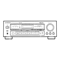
Compares miscellaneous parts for different VSX models.

8. Panel Facilities

Rear Panel

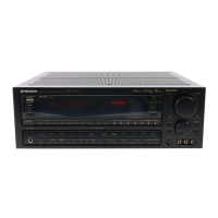
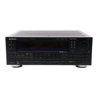
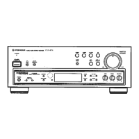
Identifies rear panel connections and controls for VSX-9500S and VSX-7500S.

FM/AM Antenna Terminals

Connects FM/AM antennas and provides hints for better reception.

Surround Input Balance Control (Dolby Surround)

Adjusts surround sound balance for optimal effect.

AC Outlets

Provides power outlets for connected equipment.

Front Panel Overview

Power Standby/On Switch

Split Screen Control

Enhancer Control

Pro Logic Center Mode Switch (VSX-9500S)

Audio/Video Input Selector Switches

Surround Mode Selector Switches

VCR 1 Mode Switch

Auto/Manual Tuning Selector Switch

Direct Access Tuning Switch

9. Specifications

Amplifier Section

Details power output and harmonic distortion for amplifier stages.

Video Section

Specifications for video input, output, response, and signal-to-noise ratio.

Audio Section

Specifications for audio damping factor, input/output levels, and response.

Surround Section

Specifications for surround input/output levels and frequency response.

FM Tuner Section

FM tuner performance specifications like frequency range, sensitivity, and distortion.

AM Tuner Section

AM tuner performance specifications like frequency range, sensitivity, and selectivity.

Miscellaneous

Power requirements, power consumption, AC outlets, dimensions, and weight.

Related product manuals