Do you have a question about the Pioneer VSX-C301-S and is the answer not in the manual?
Contains chemicals known to cause cancer or reproductive harm.
Fuse symbols indicate replacement parts must be identical.
French version of the fuse symbol notice.
Precautions for customer and technician, including leakage current check.
Information on special safety characteristics of replacement parts.
Conform to regulations and follow safety instructions during servicing.
Essential for maintaining original performance; follow manual instructions.
Proper cleaning required to restore performance of optical pickups and heads.
Procedures to protect product from transit damage.
Use prescribed lubricants/glues and parts for performance and reliability.
Details continuous average power output and RMS power output specs.
Specifies input sensitivity, impedance, output level, and impedance.
Lists FM frequency range, sensitivity, S/N ratio, distortion, and selectivity.
Details AM frequency range, sensitivity, selectivity, and S/N ratio.
Covers power requirements, consumption, dimensions, and weight.
Lists accessories included with the product.
Exploded view and parts list for product packaging.
Lists parts for the exterior of the unit.
Lists parts for the interior of the unit.
Lists parts for the front panel assembly.
Shows the overall functional blocks and interconnections.
Details the signal flow for audio and video processing.
Illustrates the different power supply circuits.
Shows how various assemblies are interconnected.
Schematic for the FM front-end circuitry.
Schematic for the AM RF tuning block.
Schematic of the video processing block.
Schematic of the audio input circuitry.
Schematic of the first part of the mother board.
Schematic of the second part of the mother board.
Schematic of the DSP KAWA assembly.
Schematic of the third part of the mother board.
Schematic of the fourth part of the mother board.
Schematic of the fifth part of the mother board.
Schematic of the first part of the DSP assembly.
Schematic of the second part of the DSP assembly.
Schematic of the Front In assembly.
Schematic of the Amp Kawa assembly.
Schematic of the 6-channel amplifier circuit.
Schematic of the amplifier output stage.
Schematic of the encoder assembly.
Schematic of the front assembly.
Schematic of the power switch assembly.
Schematic of the primary power supply section.
Schematic of the 5V power supply.
Schematic of the 12V power supply.
Schematic of the VHVL power supply.
Explanation of symbols used in PCB diagrams.
Illustrates the viewpoint of PCB diagrams.
Component layout for the FM/AM tuner module (Side A).
Component layout for the FM/AM tuner module (Side B).
Component layout for the Audio Input assembly.
Component layout for the 12V assembly.
Component layout for the Mother board.
Component layout for the DSP KAWA assembly.
Component layout for the D5V assembly.
Component layout for the DSP assembly (Side A).
Component layout for the DSP assembly (Side B).
Component layout for the Front In assembly (Side A).
Component layout for the Front In assembly (Side B).
Component layout for the Amp Kawa assembly (Side A).
Component layout for the Amp Kawa assembly (Side B).
Component layout for the 6-channel amplifier assembly (Side A).
Component layout for the 6-channel amplifier assembly (Side B).
Component layout for the Amp Out assembly (Side A).
Component layout for the Amp Out assembly (Side B).
Schematic of the encoder assembly.
Schematic of the front assembly.
Schematic of the power switch assembly.
Component layout for the Encoder assembly.
Component layout for the Front assembly.
Component layout for the Encoder assembly.
Component layout for the Primary assembly (Side A).
Component layout for the Primary assembly (Side B).
Component layout for the VHVL assembly (Side A).
Component layout for the VHVL assembly (Side B).
Component layout for the Video assembly (Side A).
Component layout for the Video assembly (Side B).
Lists major assemblies and their part numbers.
Lists semiconductor components used in the unit.
Lists capacitor components and their specifications.
Lists resistor components and their specifications.
Details adjustment procedures for the tuner section.
Specific adjustment steps for the FM tuner.
Information on diagnosing unit operation and modes.
Procedures and functions for entering and using the test mode.
Describes the DC detection protection circuit.
Describes the overload detection protection circuit.
Describes protection for fan and power supply circuits.
Describes protection for fan stop conditions.
Explains the benefits of automatic speaker detection.
Details how speaker detection is performed.
Outlines speaker settings based on detection results.
How user settings interact with detected speaker configurations.
Explains the amplifier power circuit protection.
Describes the fan detection circuit and its protection function.
Step-by-step guide for diagnosing and resolving issues.
Method for recovering from microcomputer hang-up.
Shows the sequence of operations during power on.
Shows the sequence of operations during power off.
Illustrates timing during function changes.
Illustrates timing for events other than function changes.
Comprehensive list of integrated circuits used in the unit.
Pinout details for the main microcomputer.
Pinout details for the display microcomputer.
Information on the front panel FL display.
Pinout details for the display module.
Layout of the display grids.
Designation of display segments.
Details of pin connections for the display.
Instructions for cleaning specific components.
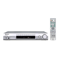
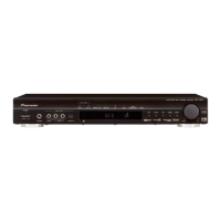
Description of the front panel controls and indicators.
Explains the meaning of various display indicators.
Crucial notes before making connections.
Details for connecting speakers.
Instructions for connecting antennas.
Information on control in/out jacks.
Connections for AC power and subwoofer.
How to connect digital audio sources.
Connections for various audio and video signals.
How to operate the remote in different modes.
Buttons for selecting audio/video inputs.
Controls for speaker setup and level adjustment.
Buttons for selecting sound modes and processing.
How to select sound modes and dialog enhancement.
Controls for muting, signal selection, and volume adjustment.
Controls for system setup and menu navigation.
Controls for virtual surround back and display dimming.
Controls for external playback and channel selection.
Procedure to reset remote control presets to factory defaults.
Steps to reset the receiver to factory default settings.
Lists the factory default settings for various parameters.