Do you have a question about the Pioneer VSX-LX301 and is the answer not in the manual?
Explanation of how to interpret the suffix codes used for model identification.
Provides clarification on the interpretation of model suffix codes.
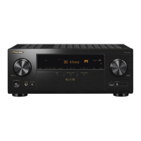
Detailed illustrations of the VSX-1131 unit's panels and included accessories.
Detailed illustration of the front panel controls and indicators.
Detailed illustration of rear panel connections and inputs/outputs.
Diagram and identification of the remote control unit.
List of accessories provided with the unit.
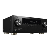
Detailed illustrations of the VSX-LX301 unit's panels and included accessories.
Detailed illustration of the front panel controls and indicators.
Detailed illustration of rear panel connections and inputs/outputs.
Diagram and identification of the remote control unit.
List of accessories provided with the unit.
Steps to save user preferences before resetting the unit.
Procedure for resetting the unit, including display indicators.
Steps to load previously saved user preferences.
Explanation of how the unit enters protect mode due to abnormal conditions.
Explanation of the diagnostic mode triggered by abnormal conditions.
Details on how the self-diagnostic function operates during power-on.
Describes the display output during and after self-diagnostics.
Procedure to confirm the cause of a protect mode activation.
Procedure to clear error information after repairs.
Method to cancel self-diagnostic mode and return to normal operation.
Steps for manually initiating the self-diagnostic process.
Procedure to check the model name and its corresponding destination.
Table correlating model names with destination and FL display codes.
General information about WiFi 5GHz settings and country code importance.
Information regarding the country code setting for processing circuit boards.
Details on default country codes set by the PRC board for destination.
Guidance on ensuring the correct country code is set for product usage.
Guidance on matching PRC board default country code with customer's country.
Illustrates situations requiring country code setup for compatibility.
List of country codes for various regions, divided into two parts.
List of country codes for North and South American regions.
List of country codes for Asian and Oceanian regions.
List of country codes for Middle Eastern regions.
Continuation of country codes for European and African regions.
List of country codes for European and African regions.
List of country codes for European and African regions.
List of country codes for European and African regions.
Instructions on how to interpret the PRC board part number.
Table mapping destination codes to PRC board default country codes.
Procedure to check the current firmware version of the unit.
Steps for downloading and preparing firmware files for update.
Instructions for entering service mode and initiating firmware updates.
Details on available firmware update modules (USB/NET) and options.
Important warning regarding maintaining firmware combination during updates.
Completion steps for firmware update, including checking version and powering off.
Steps for starting, waiting for completion, and powering off the unit.
Procedure to check the new firmware version after update.
Procedure to confirm idling current after amplifier repair.
Specifies the permissible range for idling current measurements.
Comprehensive list of all schematic diagrams included in the manual.
List of schematics by part number and function for different models.
Illustrates the signal flow for analog audio processing.
Illustrates the signal flow for analog audio processing.
Illustrates the signal flow for video processing and inputs/outputs.
Illustrates the signal flow for video processing and inputs/outputs.
Illustrates the signal flow for digital audio inputs and outputs.
Illustrates the signal flow for digital audio inputs and outputs.
Schematic diagram for the Audio Signal Processor (ASP) section.
Diagram showing components and connections within the ASP section.
Schematic diagram for the Amplifier section.
Diagram showing components and connections within the Amplifier section.
Schematic diagram for the thermal sensor circuit.
Schematic illustrating the thermal sensor and its circuit.
List of components and their variations based on destination for BAAR-1979.
Table detailing component differences based on destination.
Schematic diagram of the Class A amplifier circuit.
Schematic of the Class A amplifier circuit configuration.
Schematic diagram of the power supply unit.
Schematic of the power supply unit and its components.
Schematic for video, speaker out, and IR/12V trigger sections.
Schematic illustrating video, speaker output, and trigger circuit connections.
Schematic diagram for the RS-232C communication interface.
Schematic of the RS-232C communication interface.
Schematic diagram for the display unit.
Schematic illustrating the display unit and its connected components.
Schematic diagram for the headphone jack and related circuitry.
Schematic of the headphone output jack and associated circuitry.
Schematic diagram for the Digital-to-Analog Converter filter section.
Schematic of the Digital-to-Analog Converter filter circuitry.
Schematic diagram for the Main Microprocessor Unit (MPU).
Schematic detailing the Microprocessor Unit (MPU) and its interfaces.
Schematic diagram for the Video Signal Processor (VMPU) section.
Schematic detailing the Video Processing Unit (VMPU) and its connections.
Schematic diagram for the Video Signal Processor (VSP) section.
Schematic detailing the Video Signal Processor (VSP) and its connections.
Schematic diagram for the second HDMI receiver section.
Schematic of the second HDMI receiver and associated components.
Schematic diagram for the Digital Interface Receiver and DAC sections.
Schematic detailing the Digital Interface and Digital-to-Analog Converter sections.
Schematic diagram detailing ARM processor I/O connections.
Schematic showing ARM processor I/O pin assignments and connections.
Schematic diagram of the ARM processor power supply circuits.
Schematic illustrating the power supply circuits for the ARM processor.
Schematic diagram detailing the ARM processor memory interfaces.
Schematic showing the memory interfaces for the ARM processor.
Schematic diagram for ARM USB, Ethernet, and WiFi connectivity.
Schematic detailing the USB, Ethernet, and WiFi module connections.
Schematic diagram illustrating the unit's power supply.
Schematic illustrating the various voltage rails provided by the power supply.
Schematic diagram for the tuner section.
Schematic of the tuner section, including RF components.
Schematic diagram for the front HDMI input section.
Schematic of the front HDMI input and associated I2C bus repeater.
General overview and exploded view of the VSX-1131 unit.
Information regarding the WiFi/Bluetooth module certification and placement.
Mandatory compliance statements for FCC and Industry Canada.
General overview and exploded view of the VSX-LX301 unit.
Information regarding the WiFi/Bluetooth module certification and placement.
Mandatory compliance statements for FCC and Industry Canada.
Exploded view identifying parts of the front section assembly.
Identification of parts and components on the front panel assembly.
Exploded view identifying parts of the rear section assembly for VSX-1131.
Identification of parts and components on the rear panel assembly.
Exploded view identifying parts of the rear section assembly for VSX-LX301.
Identification of parts and components on the rear panel assembly.
Exploded view identifying parts of the amplifier section.
Identification of parts and components within the amplifier section.
Diagram showing the exploded view of the packing process.
Diagram illustrating the final packing process for the unit.
List of all available models and their full names.
List correlating full model names with their abbreviated designations.
Lists mapping button actions to different model designations (List-A to List-E).
Explanation of button operation descriptions using simplified expressions.
Procedure to check the MAIN checksum using specific button sequences.
Steps for setting the unit to shipping mode, including clearing data.
Procedure to verify FL tube and LED operation using specific button sequences.
Instructions on how to access the HDMI resolution display mode.
How to view input and output signals in HDMI resolution display mode.
Details on normal input signal formats and their display representations.
Shows display formats for various digital input signals (DVI, VGA, CVBS).
Shows display formats for analog input signals (CVBS, Component).
Details on normal output signal formats and their display representations.
Details output resolution, color space, and bit depth for various signals.
Details on 3D input signal formats and their display representations.
Displays aspect ratios and 3D format information.
Details on PC input signal formats and their display representations.
Shows display formats for PC input resolutions.
Procedure to check and verify the cooling fan's operation.
Table correlating thermal sensor levels with VOLH port voltage.
Defines temperature ranges for thermal sensor readings.
Defines voltage levels for the VOLH port corresponding to fan speeds.
Explanation of how the service information display system works.
Steps to access and display service information.
Procedure to navigate and change history numbers in service mode.
Steps to exit service information mode and return to normal display.
Reference table for codes representing various audio listening modes.
Reference table for codes representing various audio listening modes.
List of parts related to the cabinet, chassis, screws, and nuts.
List of transistors, diodes, and other semiconductor components.
List of transformers, coils, and switches used in the unit.
List of frontend unit parts, wires, and accessories.
List of packing materials and accessory items.
Identification of packing materials like pads, sheets, and cartons.
Identification of accessories such as remote control, MIC, and antennas.
List of cabinet, chassis, screws, and nuts for VSX-1131(B)MDF.
List of semiconductor components for the VSX-1131(B)MDF model.
List of transformers, coils, and switches for VSX-1131(B)MDF.
List of frontend parts and accessories for VSX-1131(B)MDF.
List of packing materials and accessories for VSX-1131(B)MDF.
Identification of packing materials for VSX-1131(B)MDF.
Identification of accessories for VSX-1131(B)MDF.
List of cabinet, chassis, screws, and nuts for VSX-1131(B)MMA.
List of semiconductor components for the VSX-1131(B)MMA model.
List of transformers, coils, and switches for VSX-1131(B)MMA.
List of frontend parts and accessories for VSX-1131(B)MMA.
List of packing materials and accessories for VSX-1131(B)MMA.
Identification of packing materials for VSX-1131(B)MMA.
Identification of accessories for VSX-1131(B)MMA.
List of cabinet, chassis, screws, and nuts for VSX-1131(B)MMB.
List of semiconductor components for the VSX-1131(B)MMB model.
List of transformers, coils, and switches for VSX-1131(B)MMB.
List of frontend parts and accessories for VSX-1131(B)MMB.
List of packing materials and accessories for VSX-1131(B)MMB.
Identification of packing materials for VSX-1131(B)MMB.
Identification of accessories for VSX-1131(B)MMB.
List of cabinet, chassis, screws, and nuts for VSX-1131(B)MMP.
List of semiconductor components for the VSX-1131(B)MMP model.
List of transformers, coils, and switches for VSX-1131(B)MMP.
List of frontend parts and accessories for VSX-1131(B)MMP.
List of packing materials and accessories for VSX-1131(B)MMP.
Identification of packing materials for VSX-1131(B)MMP.
Identification of accessories for VSX-1131(B)MMP.
List of cabinet, chassis, screws, and nuts for VSX-1131(B)MMR.
List of semiconductor components for the VSX-1131(B)MMR model.
List of transformers, coils, and switches for VSX-1131(B)MMR.
List of frontend parts and accessories for VSX-1131(B)MMR.
List of packing materials and accessories for VSX-1131(B)MMR.
Identification of packing materials for VSX-1131(B)MMR.
Identification of accessories for VSX-1131(B)MMR.
List of cabinet, chassis, screws, and nuts for VSX-1131(S)MMP.
List of semiconductor components for the VSX-1131(S)MMP model.
List of transformers, coils, and switches for VSX-1131(S)MMP.
List of frontend parts and accessories for VSX-1131(S)MMP.
List of packing materials and accessories for VSX-1131(S)MMP.
Identification of packing materials for VSX-1131(S)MMP.
Identification of accessories for VSX-1131(S)MMP.
List of cabinet, chassis, screws, and nuts for VSX-LX301(B)MDC.
List of semiconductor components for the VSX-LX301(B)MDC model.
List of transformers, coils, and switches for VSX-LX301(B)MDC.
List of frontend parts and accessories for VSX-LX301(B)MDC.
List of packing materials and accessories for VSX-LX301(B)MDC.
Identification of packing materials for VSX-LX301(B)MDC.
Identification of accessories for VSX-LX301(B)MDC.
List of components for the BAAF-1979-1AG board.
List of semiconductor components for the BAAF-1979-1AG board.
List of transformers, coils, and capacitors on the BAAF-1979-1AG board.
List of transformers and coils on the BAAF-1979-1AG board.
List of capacitor components for the BAAF-1979-1AG board.
Continuation of capacitor list for the BAAF-1979-1AG board.
Continuation of the capacitor list for the BAAF-1979-1AG board.
List of resistor components for the BAAF-1979-1AG board.
List of resistor components for the BAAF-1979-1AG board.
List of switches, terminals, and wires on the BAAF-1979-1AG board.
List of switches, terminals, and wires on the BAAF-1979-1AG board.
List of components for the BADIS-2015-1E board.
List of semiconductor components for the BADIS-2015-1E board.
List of capacitor components for the BADIS-2015-1E board.
List of capacitor components for the BADIS-2015-1E board.
Continuation of capacitor list for the BADIS-2015-1E board.
Continuation of capacitor list for the BADIS-2015-1E board.
List of resistor components for the BADIS-2015-1E board.
List of resistor components for the BADIS-2015-1E board.
List of switches, terminals, and wires on the BADIS-2015-1E board.
List of switches, terminals, and wires on the BADIS-2015-1E board.
List of components for the BADIS-2015-1G board.
List of semiconductor components for the BADIS-2015-1G board.
List of capacitor components for the BADIS-2015-1G board.
List of capacitor components for the BADIS-2015-1G board.
Continuation of capacitor list for the BADIS-2015-1G board.
Continuation of capacitor list for the BADIS-2015-1G board.
List of resistor components for the BADIS-2015-1G board.
List of resistor components for the BADIS-2015-1G board.
List of switches, terminals, and wires on the BADIS-2015-1G board.
List of switches, terminals, and wires on the BADIS-2015-1G board.
List of components for the BATRM-2023-1AE board.
List of semiconductor components for the BATRM-2023-1AE board.
List of capacitor components for the BATRM-2023-1AE board.
List of capacitor components for the BATRM-2023-1AE board.
List of switches, terminals, and wires on the BATRM-2023-1AE board.
List of switches, terminals, and wires on the BATRM-2023-1AE board.
List of components for the BATRM-2023-1AG board.
List of semiconductor components for the BATRM-2023-1AG board.
List of components for the BADIS-2015-1G board.
List of semiconductor components for the BADIS-2015-1G board.
List of capacitor components for the BADIS-2015-1G board.
List of capacitor components for the BADIS-2015-1G board.
List of components for the BADIS-2015-1E board.
List of semiconductor components for the BADIS-2015-1E board.
List of capacitor components for the BADIS-2015-1E board.
Continuation of capacitor list for the BADIS-2015-1E board.
List of resistor components for the BADIS-2015-1E board.
List of resistor components for the BADIS-2015-1E board.
List of components for the BATRM-2023-1AE board.
List of semiconductor components for the BATRM-2023-1AE board.
List of capacitor components for the BATRM-2023-1AE board.
List of capacitor components for the BATRM-2023-1AE board.
List of components for the BATRM-2023-1AG board.
List of semiconductor components for the BATRM-2023-1AG board.
| Channels | 7.2 |
|---|---|
| THD | 0.08% |
| Impedance | 8 ohms |
| HDMI Outputs | 2 |
| HDMI Version | 2.0a |
| HDCP Version | 2.2 |
| 4K Ultra HD Upscaling | Yes |
| Dolby Atmos | Yes |
| DTS:X | Yes |
| MCACC Auto Room Tuning | Yes |
| Wi-Fi | Yes |
| Bluetooth | Yes |
| AirPlay | Yes |
| Google Cast | Yes |
| Phono Input | Yes |
| Multi-Room Audio | Yes |
| Input Sensitivity | 200 mV |
| Ethernet Port | Yes |
| Power Output per Channel | 100 W (8 ohms, 20 Hz-20 kHz, THD 0.08 %) |
| HDMI Inputs | 7 |
| HDR Support | HDR10, Dolby Vision, HLG |
| Streaming Services | Spotify, TIDAL, Deezer, TuneIn |
| USB | 1 (Front) |
| Signal-to-Noise Ratio | 106dB |
| Supported Audio Formats | MP3, WMA, AAC, FLAC, ALAC, WAV, AIFF, DSD |