EasyManua.ls Logo

Pioneer YN012ALFI19RPD User Manual

Pioneer YN012ALFI19RPD
39 pages
To Next Page IconTo Next Page
Page #1 background imageLoading...
Page #1 background image
CS78421-548-754
DUCTLESS MINI SPLIT SYSTEM AIR CONDITIONER / HEAT PUMP
IMPORTANT NOTICE:
Please read this manual carefully before installing
or operating your new air conditioning system.
Be sure to save this manual for future reference.
Service Manual
WYT Inverter Series
For
9,000-36,000 BTU/hr Systems

Table of Contents

Question and Answer IconNeed help?

Do you have a question about the Pioneer YN012ALFI19RPD and is the answer not in the manual?

Pioneer YN012ALFI19RPD Specifications

General IconGeneral
Cooling Capacity12000 BTU/h
SEER Rating19
Heating Capacity12000 BTU/h
Power Supply1 Phase, 60 Hz
RefrigerantR410A

Summary

Service Manual

Important Notice

Operation Details

Electronic Controller

Safety Protection

Details various safety protection mechanisms implemented in the electronic controller for safe operation.

HEATING Mode Operation Details

Indoor exchanger overheat protection

Details the protection mechanism when the indoor exchanger temperature becomes too high.

Protection and Failure Display

Details how error codes and protection indicators are displayed on the unit.

Error list

Protection display code list

Provides a list of protection types and their corresponding function indicators (flash codes) and digital LED codes.

Display on outdoor power source board

Wiring diagram

Precaution

SAFETY RULES AND RECOMMENDATIONS FOR THE INSTALLATION

Provides essential safety rules and recommendations for the proper installation of the air conditioner unit.

SAFETY RULES AND RECOMMENDATIONS FOR THE USER

SAFETY RULES AND PROHIBITIONS

Installation manual

Installation Details

Provides detailed information and specifications required for the installation process.

Installation for the first time

Indoor unit

Guidelines for the proper installation of the indoor unit, including placement and clearances.

OUTDOOR UNIT

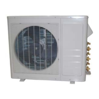
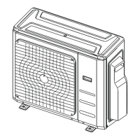
Guidelines for the proper installation of the outdoor unit, including placement and clearances.

Refrigerant piping connection

Electronic connections

Trouble shooting

Examples of repairing

Display E1 or E2

Troubleshooting guide for error codes E1 and E2 related to sensor connections or damage.

Display E6

Troubleshooting guide for error code E6 related to the indoor motor connection or damage.

Display E3, E7

Display E8

Troubleshooting guide for error code E8 related to the outdoor discharge pipe temperature sensor.

Display E0,E5

Display EA

Troubleshooting guide for error code EA related to a current sensor fault.

Display E9 (first display P0 or P9)

Display EU

Troubleshooting guide for error code EU related to voltage sensor damage.

Display EE

MALFUNCTION (PARTS) CHECK METHOD

Procedure for determining defective outdoor unit IPM/compressor

Flow chart for diagnosing malfunctions related to the outdoor unit IPM or compressor.

DC Over Current Error

E0,E5 Error

Related product manuals