EasyManua.ls Logo

Pittsburgh Automotive 62325 User Manual

Pittsburgh Automotive 62325
12 pages
To Next Page IconTo Next Page
Page #1 background imageLoading...
Page #1 background image
!"#"$%&'(%)*+#"$*%,$-%.$$/-00)))1.,(+&(2(*"3.$14&5
65,"7%&'(%$*4.8"4,7%#'//&($%,$-%/(&9'4$#'//&($:.,(+&(2(*"3.$14&5
Owners Manual & Safety Instructions
Save This Manual%Keep this manual for the safety warnings and precautions, assembly,
operating, inspection, maintenance and cleaning procedures. Write the product’s serial number in the
back of the manual near the assembly diagram (or month and year of purchase if product has no number).
Keep this manual and the receipt in a safe and dry place for future reference. 17i
When unpacking, make sure that the product is intact
and undamaged. If any parts are missing or broken,
please call 1-888-866-5797 as soon as possible.
Copyright
©
2014 by Harbor Freight Tools
®
. All rights reserved.
No portion of this manual or any artwork contained herein may be reproduced in
any shape or form without the express written consent of Harbor Freight Tools.
Diagrams within this manual may not be drawn proportionally. Due to continuing
improvements, actual product may differ slightly from the product described herein.
Tools required for assembly an d se rv ic e may n ot b e in cl uded.
;*,9%$."#%5,$*(",7%+*2&(*%'#"83%$."#%/(&9'4$1%
<,"7'(*%$&%9&%#&%4,8%(*#'7$%"8%#*("&'#%"8='(>1%
?@!6%ABC?%D@EF@G1
Question and Answer IconNeed help?

Do you have a question about the Pittsburgh Automotive 62325 and is the answer not in the manual?

Pittsburgh Automotive 62325 Specifications

General IconGeneral
BrandPittsburgh Automotive
Model62325
CategoryLifting Systems
LanguageEnglish

Summary

Key Safety Information

Assembly Precautions

Safety guidelines for assembling the product correctly and safely.

Use Precautions

Safety guidelines for operating the lift safely and effectively.

Assembly Steps

Prepare Lift Arm/Shaft Assembly

Prepare the lift arm and shaft assembly by moving safety lock levers to unlocked position.

Install Ram

Position and secure the ram into the lift arm/shaft assembly using pins and clips.

Connect Lift Arm/Shaft Assembly to Base

Secure the lift arm/shaft assembly to the base using bolts, washers, and nuts.

Attach Extension Beam

Insert and secure the extension beam to the upper lift arm with a pin and clip.

Install Wheel Brackets

Slide wheel brackets onto the extension beam and secure them with width pins.

Attach Wheel Bracket Rods

Insert wheel bracket rods through wheel brackets and secure with washers and clips.

Install Foot Pedal

Insert and secure the foot pedal to its holder on the ram using a bolt and washer.

Install Handle

Insert and secure the handle to the lift arm/shaft assembly bracket with a bolt and washer.

Components Overview

Safety Lock Lever Positions

Illustrates the safety lock levers in both locked and unlocked states.

Operating Instructions

Bleeding Hydraulic System

Procedure to remove excess air from the hydraulic system for proper operation.

Lifting Procedure

Instructions on how to safely lift a mower or ATV onto the lift.

Lowering Procedure

Procedure for safely lowering a lifted mower or ATV.

Maintenance and Servicing

Cleaning, Maintenance, and Lubrication

Guidelines for cleaning, routine maintenance, and lubrication of the lift.

Troubleshooting Guide

Identifies common problems and their probable solutions for a malfunctioning lift.

Parts List

Parts Description and Quantity

Detailed list of all parts with their descriptions and quantities.

Assembly Diagram

Component Identification Diagram

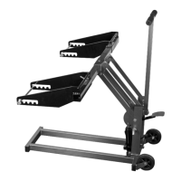
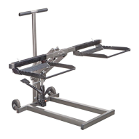
Visual representation of the lift's components with numerical labels.

Limited 90 Day Warranty

Warranty Terms and Conditions

Details the warranty period, exclusions, and procedures for claims.

Related product manuals