Step 4) Place the Ring Assembly Spacer (#6) inside the arms of the Ring Assembly/Die Receiver
(#10) between the back two holes-see Figure 1. Insert the Mounting Bolt (#15) through the
Ring Assembly/Die Receiver (#10), through the Ring Assembly Spacer (#6) and through the
bottom hole in the Ring Assembly/Die Receiver. Tighten it into place with the remaining Nut
(#14).
Step 5) The Inner Handle (#8) slides into the Outer Handle/ Die Receiver (#9) and is held in place by a
Handle Pin and Hair Clip (#12). The Inner Handle (#8) can be fully extended by pulling out
the Handle Pin and Hair Clip (#12) and pulling out the Inner Handle until the hole in the Outer
Handle (#9) lines up with the holes at the end of the Inner Handle (#8).
Step 6) Place the Outer Handle Die Receiver (#9) between the Die Receiver (#10) and secure it in place
using one of the Long Hitch Pins (#1).
Basic Operation
Following are instructions on the primary uses of your Compact Bender. Additionally, information is included
on the many ways to use your Compact Bender, along with specific examples. Becoming familiar with the
Compact Bender and its many uses will allow you to make a variety of useful items.
As the operator, you will have to decide on the way in which you will be using your Compact Bender. The
following are the basic steps you will need to take when working with the Compact Bender.
Use an appropriate measuring device to measure and:
• Decide on material and measurements to be used.
• Decide on the appropriate Die. Decide on the best placement of the Die for your particular bend.
• Decide on the appropriate attachment, Stop Block or Right Angle Bend. Correct orientation of Stop Block.
• Insert stock into the Bender and position it properly. Make the first bend.
• Check the angle and direction of the bend.
• Make all consequent bends. Adjust the workpiece as needed.
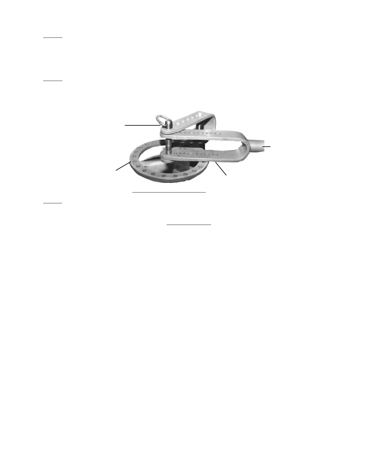
Figure 2-Assemble Handle
Ring Assembly/Die Receiver (#10)
Long Hitch Pin (#1)
#31980 Page 5
Outer Handle/Die Receiver (#9)
Inner Handle (#8)
not shown
Warning: Keep fingers and hands away from moving parts at all times.
 Loading...