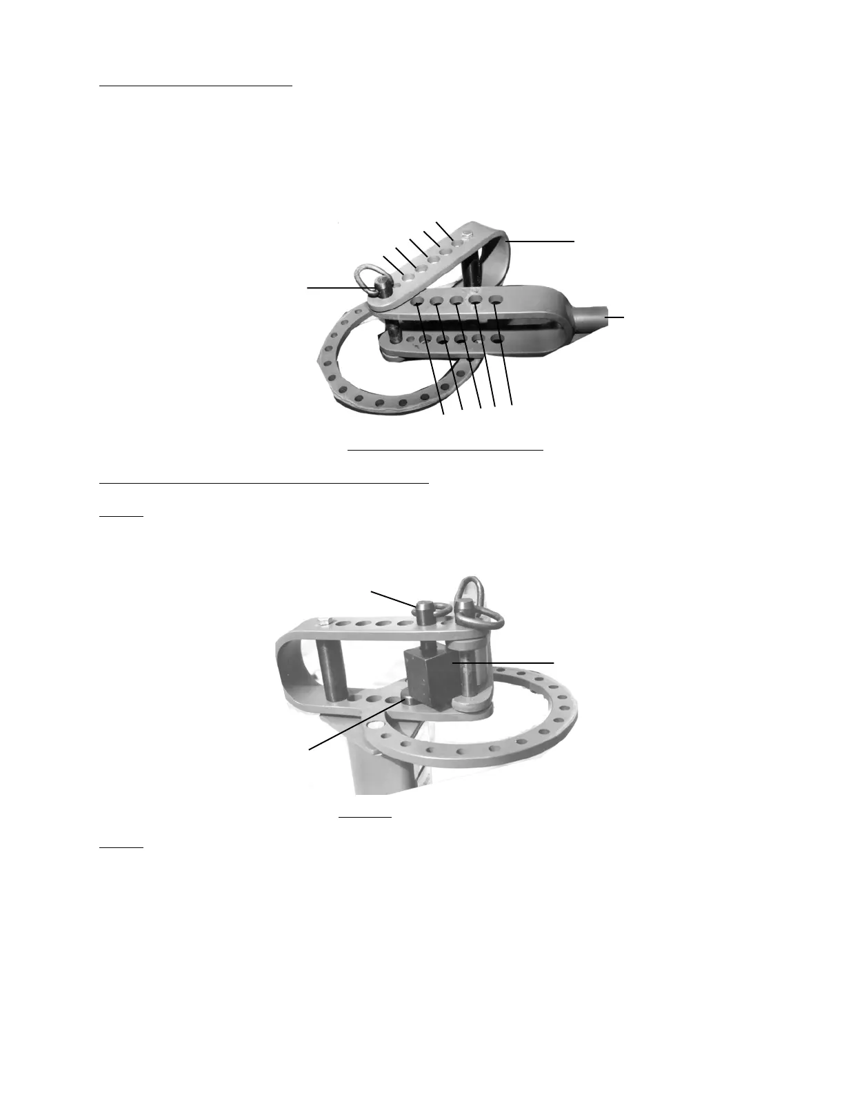
How the Holes Are Numbered
Throughout this manual, the holes are often identified by a specific number, i.e., the 3rd hole in
the Handle. There are five (5) holes referred to in the Outer Handle/Die Receiver (#9) and
5 holes referred to in the Ring Assembly (#10). For clarification of each hole and its
corresponding number, please refer to Figure 3 below.
Use of the Support Pin with the Square Stop Block
Step 1) Place the Support Pin (#5) into the hole under the Square Stop Block (#3) so that the Square
Stop Block (#3) will sit correctly in relation to the Ring Assembly/ Die Receiver-see Figure 4.
Step 2) Insert the Support Pin (#5) in the hole so that it sits under the Stop Block but does not block
the Long Hitch Pin (#1) from going through the hole in the Stop Block and into the lower hole
in the Ring Assembly (#10).
If the Stop Block is correctly placed you should not have to clamp the workpiece into place. When working with
exacting bends, however, it may be helpful to clamp the workpiece into place using vise-grip pliers.
#31980 Page 6
1
2
3
4
5
1
23
45
Center Point
Outer Handle (#9)
Ring Assembly (#10)
Figure 3 - Numbering of Holes
Long Hitch Pin (#1)
Support Pin (#5)
Square Stop Block (#3)
Figure 4
 Loading...