ENGLISH (Translated from Italian) ENGLISH (Translated from Italian) ENGLISH (Translated from Italian)
ENGLISH (Translated from Italian)
ENGLISH (Translated from Italian) ENGLISH (Translated from Italian)
A TABLE OF CONTENTS
A TABLE OF CONTENTS
B MACHINE AND MANUFACTURER
IDENTIFICATION
C MACHINE DESCRIPTION
C1 DEFINITION OF CLASS AND GROUPS
C2 INTENDED USE
C3 HANDLING AND TRANSPORT
D GENERAL WARNINGS
E FIRST AID RULES
F GENERAL SAFETY RULES
G TECHNICAL DATA
G1 PERFORMANCE SPECIFICATIONS
H ELECTRICAL DATA
I OPERATING CONDITIONS
I1 ENVIRONMENTAL CONDITIONS
I2 ELECTRICAL POWER SUPPLY
I3 DUTY CYCLE
I4 FLUIDS PERMITTED
L INSTALLATION
L1 POSITIONING, CONFIGURATIONS AND
ACCESSORIES
L2 NOTES ON SUCTION AND
DELIVERY LINES
M CONNECTIONS
M1 ELECTRICAL CONNECTIONS
M2 PIPING CONNECTIONS
N INITIAL START-UP
O EVERY DAY USE
P MAINTENANCE
Q NOISE LEVEL
R PROBLEMS AND SOLUTIONS 1
S DEMOLITION AND DISPOSAL
T EXPLODED VIEWS
B MACHINE AND MANUFACTURER
IDENTIFICATION
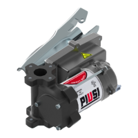
AVAILABLE MODELS: EX50 - EX75
MANUFACTURER: PIUSI S.p.A. ,
Via Pacinotti 16/A – z.i. Rangavino
46029 Suzzara - Mantova (Italy)
C MACHINE DESCRIPTION
PUMP
SELF-PRIMING, VOLUMETRIC, ROTATING ELECTRIC VANE PUMP,
EQUIPPED WITH BY-PASS VALVE.
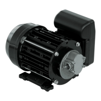
MOTOR
BRUSH MOTOR POWERED BY CONTINUOUS CURRENT, LOW VOLT-
AGE, WITH INTERMITTENT CYCLE, CLOSED TYPE, IP55 PROTECTION
CLASS ACCORDING TO CEI EN 60034-5, FLANGE-MOUNTED DI-
RECTLY TO THE PUMP BODY.
WARNING
MOTOR EQUIPPED WITH AUTOMATIC THERMAL OVER-
LOAD PROTECTION. SHOULD THE PROTECTION ACTIVATE,
TURN OFF THE PUMP AND WAIT FOR IT TO COOL DOWN.
C1 DEFINITION OF CLASS AND GROUPS
FOREWORD
Denition of class and groups
CLASS I
Flammable gases, vapors or liquids
CLASS II
Combustible dusts
CLASS III
Ignitable bers & yings
GROUP A
Acetylene
GROUP B
Flammable gas, flammable liquid–produced vapor, or combustible liquid–pro-
duced vapor
mixed with air that may burn or explode, having either a maximum experimental
safe gap (MESG) value
less than or equal to 0.45 mm or a minimum igniting current ratio (MIC ratio) less
than or equal to 0.40.
GROUP C
Flammable gas, ammable liquid–produced vapor, or combustible liquid–pro-
duced vapor
Mixed with air that may burn or explode, having either a maximum experimen-
tal safe gap (MESG) value
Greater than 0.45 mm and less than or equal to 0.75 mm, or a minimum igniting
current ratio (MIC ratio)
Greater than 0.40 and less than or equal to 0.80.
GROUP D
Flammable gas, ammable liquid–produced vapor, or combustible liquid–pro-
duced vapor
Mixed with air that may burn or explode, having either a maximum experimen-
tal safe gap (MESG) value
Greater than 0.75 mm or a minimum igniting current ratio (MIC ratio) greater
than 0.80.
CLASS I CLASS II
CLASS III
GROUP D GROUP A
GROUP B
GROUP C
C2 INTENDED USE
INTENDED
USE
THE DETERMINATION OF THE AREAS (ZONES) IS TO BE CARRIED
OUT BY THE USER
FORBIDDEN
USE
Using the appliance for uids other than those listed at paragraph
“L4 – Fluids permitted” and for uses other than those described at
the item “authorised use” is forbidden.
UNINTENDED
USE
Using the system for purposes other than those intended and indi-
cated under “Intended use” is strictly forbidden.
All other uses excepting those for which the litre counter was de-
signed and described in this manual shall be deemed “MISUSE”, and
consequently Piusi S.p.A. disclaims all liability for any injury caused
to persons of animals or damage to things or the system itself.
PLANT OPERATION RESTRICTIONS IT IS FORBIDDEN:
1
To use the appliance in a construction conguration other than that
contemplated by the manufacturer
2
To use the appliance with xed guards tampered with or removed.
3
To use the appliance in places where there is risk of explosion and/
or res classied in the following class : class II and class III and fol-
lowing groups : A , B , C.
4
To integrate other systems and/or equipment not considered by the
manufacturer in the executive project.
5
To connect the appliance up to energy sources other than those
contemplated by the manufacturer
6
To use the commercial devices for purposes other than those indi-
cated by the manufacturer.
7
Do not use in case of lightnings
C3 HANDLING AND TRANSPORT
Due to the limited weight and dimensions of the pumps, special lifting equipment is not required to
handle them. The pumps are carefully packed before dispatch. Check the packing when receiving
the material and store in a dry place.
D GENERAL WARNINGS
Important pre-
cautions
To ensure operator safety and to protect the pump from poten-
tial damage, workers must be fully acquainted with this instruc-
tion manual before performing any operation.
Symbols used
in the manual
The following symbols will be used throughout the manual to high-
light safety information and precautions of particular importance:
DANGER
DANGER indicates a hazardous situation which, if not avo-
ied will result in death or serious injury.
WARNING
WARNING indicates a hazardous situation which, if not
avoided, could result in death or serious injury
NOTICE
NOTICE is used to address pratices not related to personal
injury
Manual preser-
vation
his manual should be complete and legible throughout. It should
remain available to end users and specialist installation and main-
tenance technicians for consultation at any time.
Reproduction
rights
This manual belongs to Piusi S.p.A., which is the sole proprietor of
all rights indicated by applicable laws, including, by way of exam-
ple, laws on copyrights. All the rights deriving from such laws are
reserved to Piusi S.p.A.: the reproduction, including partial, of this
manual, its publication, change, transcription and notication to
the public, transmission, including using remote communication
media, placing at disposal of the public, distribution, marketing
in any form, translation and/or processing, loan and any other
activity reserved by the law to Piusi S.p.A..
NOTICE
THIS MANUAL IS VALID ONLY FOR DC PUMPS
ALWAYS USE THE RIGHT VOLTAGES TO CONNECT THE
PUMPS
WARNING
• For ground-based refueling only. Do not use in or on
the aircraft.
• User should consult NFPA 407 Standard for Aircraft
Fuel Servicing for safety requirements during ground fuel
servicing of aircraft using liquid petroleum fuels. This prod-
uct has no actual or implied compiance with this standard.
USE THE PUMP ONLY WITH FLUIDS PERMITTED.
DO NOT USE WITH FLUIDS NOT PERMITTED TO AVOID
DAMAGING THE PUMP. THE GUARANTEE LAPSES IN
CASE OF MISUSE OF THE FLUID.
DO NOT USE THE PUMP WITH LIQUID FOOD PRODUCTS
AND/OR WATER-BASED FLUIDS.
DO NOT OPERATE THE PUMP DRY TO AVOID DAMAGE.
Before connection, make sure that the piping and the
suction tank are free of dirt and solid residue that could
damage the pump and its accessories. NEVER COLLECT
THE FLUID FROM THE BOTTOM OF THE TANK SINCE IT
MAY CONTAIN IMPURITIES
BEFORE USING THE PUMP SWITCH OFF ALL THE ELEC-
TRONIC DEVICES ( I.E. MOBILE PHONES, BEEPERS ETC.)
E FIRST AID RULES
Contact with
the product
In the event of problems developing following EYE/SKIN CONTACT,
INHALATION or INGESTION of the treated product, please refer to
the SAFETY DATA SHEET of the uid handled.
Persons who
have suered
electric shock
Disconnect the power source, or use a dry insulator to protect yourself
while you move the injured person away from any electrical conduc-
tor. Avoid touching the injured person with your bare hands until he is
far away from any conductor. Immediately call for help from qualied
and trained personnel. Do not operate switches with wet hands.
NOTICE
Please refer to the safety data sheet for the product
SMOKING
PROHIBITED
DO NOT SMOKE NEAR THE PUMP AND DO NOT USE
THE PUMP NEAR FLAMES.
F GENERAL SAFETY RULES
USER'S
RESPONSIBIL-
ITY
IT IS ESSENTIAL TO GET TO KNOW AND UNDERSTAND
THE INFORMATION CONTAINED IN THIS MANUAL.
IT IS ESSENTIAL TO GET TO KNOW AND OBSERVE THE
SAFETY SPECIFICATIONS FOR FLAMMABLE LIQUIDS.
WARNING
Ensure that all equipment operators have access to
adequate instructions concerning safe operating and
maintenance procedures.
Essential
protective
equipment
characteristics
I
N CASE OF CONTACT WITH THE PRODUC T AND FOR GOOD STAN-
DARD OF BEHAVIOUR, wear protective equipment which is:
• suited to the operations that need to be performed;
• resistant to products used
TO DO SO, PLEASE REFER TO THE RELEVANT TECHCNICAL DATA-
SHEETS OF THE FLUID USED.
Personal pro-
tective equip-
ment that must
be worn
Safety shoes
Close-tting clothing
Protection gloves
Safety goggles
Necessary
safety
devices
Instructions manual
Protective
gloves
Prolonged contact with the treated product may cause skin irrita-
tion; always wear protective gloves during dispensing.
NOTICE
TO PREVENT ELECTRIC SHOCK AND DETONATION OF
SPARKS, ALL PUMPING SYSTEM MUST HAVE PROPER
GROUNDING, INCLUDING TANK AND ANY ACCESSORIES.
WARNING
ENFORCE REGULATIONS FOR ELECTRICAL INSTALL ATION
ALL WIRING AND ELECTRICAL CONNECTIONS MUST BE PER-
FORMED BY AUTHORIZED AND SUITABLY TRAINED PERSONNEL.
Never touch the electric plug or socket with wet hands.
Do not switch the dispensing system on if the network
connection cable or important parts of the apparatus
are damaged, such as the inlet/outlet pipe, nozzle or
safety devices. Replace the damaged pipe immediately.
WARNING
The electrical connection between the plug and socket
must be kept well away from water.
THE PUMP IS EQUIPPED WITH CURRENT-SENSING PROTEC-
TION. IF IT ACTIVATES TURN OFF THE PUMP IMMEDIATELY.
WARNING
THE PUMP IS EQUIPPED WITH PROTECTION AGAINST
OVERHEATING AND OVERLOAD RISKS. SHOULD SUCH
DEVICES ACTIVATE, THE PUMP SHUTS DOWN AUTO-
MATICALLY, BUT THE MASTER SWITCH IS NOT TURNED
OFF. IT IS IMPORTANT TO STOP THE PUMP USING ITS
SWITCH. THE PUMP RESTARTS AFTER ITS NORMAL OP-
ERATING CONDITIONS HAVE BEEN RESTORED.
FAILURE TO OBSERVE THE ABOVE MENTIONED RULES
CAN CAUSE SERIOUS ACCIDENTS
SHOULD THE HEAT SENSOR ACTIVATE UNDER NORMAL USE
CONDITIONS, PLEASE CONTACT THE TECHNICAL SUPPORT.
G TECHNICAL DATA
G1 PERFORMANCE SPECIFICATIONS
The performance diagram shows ow rate as a function of back pressure.
EX50 15 GPM
Absorption (A)
Flow Rate
(l/min) - (gpm)
Back Pressure
(bar) - (psi)
Typical delivery
configuration
12
of 3/4”
hose
Automatic
dispensing
nozzle
Functioning Point
A -
(Maximum Flow Rate)
15 57 - 15 0,2 - 3
B - (Base system) 17 40 - 10,5 0,5 - 7 • •
C - (By-Pass) 25 0 1,1 - 16 Delivery Closed
EX50 17 GPM
Absorption (A)
Flow Rate
(l/min) - (gpm)
Back Pressure
(bar) - (psi)
Typical delivery
configuration
12
3/4” hose
Manual
dispensing
nozzle
Functioning Point
A -
(Maximum Flow Rate)
15 64 - 17 0,2 - 3
B - (Base system) 17 57 - 15 0,7 - 10 • •
C - (By-Pass) 25 0 1,2 - 17.5 Delivery Closed
EX75
Absorption (A)
Flow Rate
(l/min) - (gpm)
Back Pressure
(bar) - (psi)
Typical delivery
configuration
12
of 1” hose
Automatic
dispensing
nozzle
Functioning Point
A -
(Maximum Flow Rate)
15 75 - 20 0,2 - 3
B - (Base system) 20 65 - 17 0,7 - 10 • •
C - (By-Pass) 26 0 1,1 - 17.5 Delivery Closed
WARNING
The curve refers to the following operating conditions:
Fluid: PETROL,
Temperature: 20° C
Suction conditions: The pipe and the pump position
relative to the uid level is such that a low pressure of
0.3 bar is generated at the nominal ow rate.
Under dierent suction conditions higher low pressure
values can be created that reduce the ow rate compared
to the same back pressure values. To obtain the best perfor-
mance, it is very important to reduce loss of suction pres-
sure as much as possible by following these instructions:
• shorten the suction pipe as much as possible
• avoid useless elbows or throttling in the pipes
• keep the suction lter clean
• use a pipe with a dia meter equal to, or greater than,
indicated (see Installation).
X
Y
A
B
C
0
P (bar)
H ELECTRICAL DATA
PUMP MODEL POWER SUPPLY CURRENT
Voltage (V) Frequency (Hz) Max (*) (A)
EX50
12 DC 25
EX75
12 DC 26
(*) Refers to functioning in by-pass mode.
POWER CORD INPUT
1/2" NPT
POWER CORD EX50
Minimum section recommended for cables up to 6 m:
2.5 MM^2 or 12 AWG.
Recommended sheath: H07RN-F T90°; SJT T90°; AWM Syle 21179 T80°
POWER CORD EX75
Minimum section recommended for cables up to 6 m: 12 AWG.
Recommended sheath: H07RN-F T90°; SJT T90°; AWM Syle 21179 T80°
I OPERATING CONDITIONS
I1 ENVIRONMENTAL CONDITIONS
AMBIENT
TEMPERATURE
min. +23 °F / max +104 °F
min. -10 °C / max +40 °C
FLUID
TEMPERATURE
min. +23 °F / max +104 °F
min. -10 °C / max +40 °C
RELATIVE
HUMIDITY
max. 90%
LIGHTING
The environment must conform to directive 89/654/EEC on work
environments.
In case of non-EU countries, refer to directive EN ISO 12100-2 §
4.8.6.
WARNING
The temperature limits shown apply to the pump
components and must be respected to avoid possible
damage or malfunction.
I2 ELECTRICAL POWER SUPPLY
NOTICE
The pump must be powered by DC line, the nominal
values of which are indicated on the table in the
paragraph "I - ELECTRICAL DATA".
The maximum acceptable variations from the electri-
cal parameters are:
Voltage: +/- 5% of the nominal value
WARNING
Power supply from lines with values that do not fall
within the indicated limits could cause damage to the
ELECTRICAL AND electronic components.
I3 DUTY CYCLE
NOTICE
The pumps have been designed for intermittent use
and a duty cycle of 30 min. ON and 30 min. OFF in
conditions of maximum A. TEMPERATURE (40 °C) AND
AT NOMINAL TRANSFER CONDITIONS.
WARNING
Functioning under by-pass conditions is only allowed
for short periods of time (max. 3 minutes).
I4 FLUIDS PERMITTED
WARNING
THE PUMP CAN BE USED ONLY WITH THE FOLLOW-
ING FLUIDS:
- DIESEL - KEROSENE
- PETROL - PETROL ALCOHOL MIXED MAX 15%
- AVGAS 100/100LL (PUMP ONLY ) - JET A / A1 (PUMP
ONLY)
- ASPEN 2 / 4
THE AVIO-FUELS COMPATIBILITY IS RELATED ONLY
TO THE PUMP AND NOT TO OTHER COMPONENTS
INCLUDED
(Ex. FILTER,COUNTER,NOZZLE,HOSES etc.)
L INSTALLATION
WARNING
BEFORE ANY OPERATION, ENSURE TO BE OUT OF PO-
TENTIALLY EXPLOSIVE AREAS
The pump must never be operated before the delivery and suc-
tion lines have been connected.
TIGHTEN THE ELECTRICAL BOX TO ENSURE PROTECTION AGAINST
THE RISK OF EXPLOSION. THE RIGHT CLAMPING SCREWS COUPLE
THAT GRANTS THIS PROTECTION IS 10Nm (88,5 Lbf • in).
PRELIMINARY
INSPECTION
- Verify that all components are present. Request any missing parts from the
manufacturer.
- Check that the pump has not suered any damage during transport or storage.
- Carefully clean the suction and delivery inlets and outlets, removing any dust or
other packaging material that may be present.
- Check that the electrical data corresponds to those indicated on the data plate.
- Install the pump at a height of min. 80 cm.
WARNING
IF VALVES IN THE CIRCUIT ARE TO BE INSTALLED,
MAKE SURE THEY ARE EQUIPPED WITH OVERPRES-
SURE SYSTEM.
CLEAN THE TANK AND MAKE SURE IT IS WELL-VENTILATED
(RECOMMENDED OPENING PRESSURE: 3 psi)
APPLY THE QUICK COUP LING TO THE TANK CORRECT-
LY AND SAFELY
WARNING
DO NOT BLOCK THE DRAINAGE HOLES
DANGER
I
F THE PUMP IS TO BE INSTALLED IN HAZARDOUS
(CLASSIFIED) LOCATION, IT MUST BE INSTALLED BY A
LICENSED ELECTRICIAN AND CONFIRM TO NATIONAL
FIRE PROTECTION ASSOCIATION (NFPA) CODES 30 AND
70 OR CSA 22.1. YOU AS THE OWNER , ARE RESPONSI-
BLE FOR SEEING THAT INSTALLATION AND OPERATION
OF YOUR PUMP COMPLIES WITH NFPA CODES AS WELL
AS ANY APPLICABLE STATE AND LOCAL CODES. RIGID
CONDUI MUST BE USED TO INSTALL WIRING. NOTE
THAT THE LEAD WIRES ARE FACTORY-SEALED ISOLAT-
ING THE MOTOR FROM THE JUNCTION BOX.
FAILURE TO FOLLOW THESE WIRING INSTRUCTIONS
MAY RESULTS IN DEATH OR SERIOUS INJURY FROM
SHOCK, FIRE OR EXPLOSION.
L1 POSITIONING, CONFIGURATIONS AND
ACCESSORIES
NOTICE
The pump must be secured in a stable manner.
WARNING
It is the installer's responsibility to provide the line acces-
sories necessary for the safe and proper functioning of the
pump. The accessories that are not suitable to be used with
the previously indicated material could damage the pump
and/or cause injury to persons, as well as causing pollution.
To maximise performance and prevent damage that could
affect pump operation, always demand original accessories.
L2 NOTES ON SUCTION AND
DELIVERY LINES
DELIVERY
The selection of the pump model must be made taking into account the characteristics of the system.
The combination OF: the length of the pipe, the diameter of the pipe, as well as the accessories installed,
could create back pressure that are greater than the maximum predicted pressure, thereby causing the
pump's electronic controls to intervene and reducing the dispensed flow considerably.
In these cases, to guarantee correct operation of the pump, it is necessary to reduce the resistance of
the system using pipes that are shorter or that have a greater diameter, as well as line accessories with
smaller resistances (e.g. an automatic dispensing nozzle with greater ow rate capacity).
SUCTION
Self-priming pumps are characterized by excellent suction capacity.
During the start-up phase, when the suction pipe is empty and the pump is wet with the fluid, the electric
pump unit is able to suck liquid from a maximum vertical distance of 2m.
It is important to note that it could take up to 1 minute for the pump to prime and that the presence of an
automatic dispensing nozzle on the delivery side will prevent the air trapped during the installation from be-
ing released and, therefore, the correct priming of the pump. For this reason, it is always advisable to prime the
pump without an automatic delivery nozzle, verifying the proper wetting of the pump.
Always install a foot valve to prevent the suction pipe from being emptied and to keep the pump wet at all
times. In this way, the pump will always start up immediately the next times it is used. When the system is in op-
eration, the pump can operate with back pressures of up to 0.5 bars on the suction inlet; beyond this point, the
pump may begin to cavitate resulting in a drop of the flow rate and an increase in the noise levels of the system.
In light of this, it is important to guarantee small back pressures on the suction side, by using short pipes with
diameters that are equal to or larger than those recommended, reducing bends to a minimum, and using
filters with a large cross-section and foot valves with minimum possible resistance on the suction side. It is very
important to keep the suction filters clean because, when they become clogged, they increase the resistance
of the system.
The vertical distance between the pump and the fluid must be kept as short as possible, and it must fall within
the 2m maximum required for priming. If the distance is greater, a foot valve must be installed to allow the
suction pipes to fill up and the diameter pipes must be larger. It is however recommended that pump not be
installed if the vertical distance is greater than 3m.
WARNING
If the suction tank is higher than the pump, an anti-siphon
valve should be installed to prevent accidental fuel leaks. Di-
mension the installation in order to control the back pressures
due to water hammering
It is a good system practice to install vacuum and air pressure
gauges right at the inlets and outlets of the pump, which allow
verication that operating conditions are within anticipated
limits. To prevent the suction pipes from being emptied when
the pump stops, a foot valve should be installed.
THE INSTALLER IS RECOMMENDED TO INSTALL A
SUCTION FILTER.
M CONNECTIONS
M1 ELECTRICAL CONNECTIONS
WARNING
BEFORE ANY OPERATION, ENSURE TO BE OUT OF PO-
TENTIALLY EXPLOSIVE AREAS
IT IS THE INSTALLER'S RESPONSIBILITY TO CARRY
OUT THE ELECTRICAL CONNECTIONS IN COMPLIANCE
WITH THE RELEVANT STANDARDS.
FOR INSTALLATION IN UNCL ASSIFIED AREAS, THE SUPPLI-
ER POWER CORD AND STRAIN RELIEF GRIP MAY BE USED
THESE COMPONENTS HAVE NOT BEEN EVALUATED AS
PART OF THE UL LISTED EQUIPMENT AND ARE NOT IN-
TENDED FOR USE IN HAZARDOUS (CLASSIFIED) LOCATION.
Comply with the following (not exhaustive) instruc-
tions to ensure a proper electrical connection:
- During installation and maintenance make sure that power supply to the
electric lines has been turned o.
- Use cables with minimum sections, rated voltages and installation type
that are suitable for the characteristics indicated in paragraph "I - ELECTRICAL
DATA" and the installation environment.
- Always make sure that the cover of the terminal strip box is closed before
switching on the power supply, after having checked the integrity of the seal
gaskets that ensure the IP55 protection grade. For those screws use a 10 nm
clamping couple
WARNING
All motors are equipped with a grounding terminal.
Make sure all the plant is properly grounded.
BE SURE TO USE A CABLE GLAND, WITH SUFFICIENT
PROTECTION GRADE (Exd)
NOTICE
IN THE EVENT OF INSTALLATION IN ZONES WHICH ARE
NOT CLASSIFIED, IT IS SUFFICIENT TO OBSERVE THE
MINIMUM SAFETY STANDARDS ALREADY MENTIONED
IN THIS MANUAL.
- THE OWNER HAS THE RESPONSIBILITY TO VERIFY
THAT ALL THE LOCAL AND NATIONAL REGULATIONS
HAVE BEEN OBSERVED.
- MAKE SURE THAT THE CABLE CONNECTING THE BAT-
TERY IS PROTECTED FROM HEAT SOURCES AND SHARP
EDGES. INSTALL THE FUSE CLOSER TO THE BATTERY.
WARNING
FAILURE TO OBSERVE THE ABOVE MENTIONED RULES
CAN CAUSE SERIOUS ACCIDENTS
Red Cable +
Black Cable -
GND
Switch
Motor
protector
t°C
1/2” NPT
INLET
M2 PIPING CONNECTIONS
FOREWORD
- Before carrying out any connection, refer to the visual indications i.e.
arrow on the pump head, to identify suction and delivery.
WARNING
Wrong connection can cause serious pump damage.
PRELIMINARY
INSPECTION
- Before connection, make sure that the piping and the suction tank are free of dirt
and solid residue that could damage the pump and its accessories. NEVER COLLECT
THE FLUID FROM THE BOTTOM OF THE TANK SINCE IT MAY CONTAIN IMPURITIES
- Before connecting the delivery pipe, partially ll the pump body, from deliv-
ery side, with the liquid that needs to be pumped in order to facilitate priming.
- Do not use conical threaded ttings, which could damage the threaded
inlet or outlet openings of the pump if excessively tightened.
N INITIAL START-UP
FOREWORD
- Check that the quantity of uid in the suction tank is greater than the
amount you wish to transfer.
- Make sure that the residual capacity of the delivery tank is greater than the
quantity you wish to transfer.
- Make sure that the piping and line accessories are in good condition.
NOTICE
THIS PUMP IS NOT PROVIDED FOR FURTHER REGULA-
TION OF DELIVERY AND PRESSURE
WARNING
Fluid leaks can damage objects and injure persons.
NOTICE
- Never start or stop the pump by connecting or cut-
ting out the power supply.
- Prolonged contact with some uids can damage the
skin. The use of goggles and gloves is recommended.
IF THE PUMP
DOES NOT PRIME
Depending on the system characteristics, the priming phase can
last from several seconds to a few minutes. If this phase is pro-
longed, stop the pump and verify:
- that the pump is not running completely dry (ll with uid from
the delivery line);
- that the suction pipe guarantees against air inltration;
- that the suction lter is not clogged;
- that the suction height is not higher than 2 mt.
- that all air has been released from the delivery pipe.
AT THE END OF
THE INITIAL
START-UP
When priming has occurred, verify that the pump is operating
within the anticipated range, in particular:
- that under conditions of maximum back pressure, the power
absorption of the motor stays within the values shown on the
identication plate;
- that the delivery back pressure does not exceed the maximum
back pressure for the pump.
O EVERY DAY USE
USE
PROCEDURE
1
If exible pipes are used, attach the ends of the piping to the tanks. In
the absence of an appropriate slot, solidly grasp the delivery pipe be-
fore beginning dispensing.
2
Before starting the pump make sure that the delivery valve is closed
(dispensing nozzle or line valve)
3
Turn the ON/OFF switch on
4
Open the delivery valve, solidly grasping the pipe
5
While dispensing, do not inhale the pumped product
6
IF ANY TREATED FLUID LEAKS OUT DURING DISPENSING, TAKE ALL
STEPS NECESSARY TO ENSURE THE LEAKED FLUID IS CLEANED UP AND
SAFE AS SPECIFIED ON THE PRODUCT TECHNICAL SHEET.
7
Close the delivery valve to stop dispensing
8
When dispensing is nished, turn o the pump
WARNING
THE WORKING OPERATIONS MUST ALWAYS BE
GUARDED BY THE OPERATOR.
The by-pass valve allows functioning with delivery
closed only for short periods (max. 3 minutes).
To avoid damaging the pump, after use, make sure
the pump is o.
In case of a power break, switch the pump o straight away.
Should any sealants be used on the suction and de-
livery circuit of the pump, make sure that these prod-
ucts are not released inside the pump.
Foreign bodies in the suction and delivery circuit of
the pump could cause malfunctioning and breakage
of the pump components.
P MAINTENANCE
Safety instruc-
tions
The PUMP IS DESIGNED AND CONSTRUCTED TO require a minimum of main-
tenance.
Before carrying out any maintenance work, DISCONNECT THE PUMP from
any electrical and hydraulic power source.
During maintenance, the use of personal protective equipment (PPE) is com-
pulsory.
In any case always bear in mind the following basic recommendations for a
good functioning of the pump
WARNING
BEFORE ANY OPERATION, ENSURE TO BE OUT OF PO-
TENTIALLY EXPLOSIVE AREAS FOR SAFETY REASONS
IT’S NOT ALLOWED TO DISASSEMBLE THESE PARTS :
(1) BOTTOM (2) MOTOR PIPE (3) PUMP BODY
FOR SAFETY REASONS IT IS FORBIDDEN TO REMOVE
THE PARTS “BOTTOM PLATE” (1), “MOTOR TUBE” (2)
AND “PUMP BODY” (3).
Authorised
maintenance
personnel
All maintenance must be performed by qualied personnel. Tampering can
lead to performance degradation, danger to persons and/or property and
may result in the warranty and UL/ATEX CERTIFICATION being voided.
Measures to be
taken
Check that the labels and plates found on the dispensing system do not dete-
riorate or become detached over time.
ONCE A WEEK:
- Check that the pipe connections are not loose to prevent any leaks;
- Check and keep the lter installed on the suction line clean.
ONCE A MONTH:
- Check the pump body and keep it clean and free of any impurities;
- Check that the electrical supply cables are in good condition.
Q NOISE LEVEL
Under normal operating conditions, noise emission of all models does not exceed
74 dB at a distance of 1 metre from the electric pump.
R PROBLEMS AND SOLUTIONS
For any problems contact the authorised dealer nearest to you.
PROBLEM POSSIBLE CAUSE CORRECTIVE ACTION
THE MOTOR IS NOT
TURNING
Lack of electric power Check the electrical connections
and the safety systems.
Rotor jammed Check for possible damage or
obstruction of the rotating com-
ponents.
Motor problems Contact the Service Depar tment
THE MOTOR TURNS
SLOWLY WHEN STARTING
Low voltage in the electric power
line
Bring the voltage back within the
anticipated limits
LOW OR NO FLOW RATE
Low level in the suction tank Rell the tank
Foot valve blocked Clean and/or replace the valve
Filter clogged Clean the lter
Excessive suction pressure Lower the pump with respect to
the level of the tank or increase the
cross-section of the piping
High loss of head in the delivery
circuit (working with the by-pass
open)
Use shorter piping or of greater
diameter
By-pass valve blocked Dismantle the valve, clean and/or
replace it
Air entering the pump or the suc-
tion piping
Check the seals of the connections
A narrowing in the suction piping Use piping suitable for working
under suction pressure
Low rotation speed Check the voltage at the pump.
Adjust the voltage and/or use
cables of greater cross-section
The suction piping is resting on the
bottom of the tank
Raise the piping
INCREASED PUMP
NOISE
Cavitation occurring Reduce suction pressure
Irregular functioning of the by-
pass
Dispense until the air is purged
from the by-pass system
Presence of air in the uid Verify the suction connections
LEAKAGE FROM THE
PUMP BODY
Seal damaged Check and replace the seal
THE PUMP DOES NOT
PRIME THE LIQUID
Suction circuit blocked Remove the blockage from the
suction circuit
Malfunction of foot valve tted on
suction circuit
Replace foot valve
The suction chambers are dry Add liquid from pump delivery
side
The pump chambers are dirty or
blocked
Remove the blockages from the
suction and delivery valves
THE HEAT SENSOR
ACTIVATES UNDER
NORMAL OPERATING
CONDITIONS
Operating fault Contact the technical support..
S DEMOLITION AND DISPOSAL
Foreword
If the system needs to be disposed, the parts which make it up must be
delivered to companies that specialize in the recycling and disposal of
industrial waste and, in particular:
Disposing of pack-
ing materials
The packaging consists of biodegradable cardboard which can be deliv-
ered to companies for normal recycling of cellulose.
Metal Parts
Disposal
Metal parts, whether paint-finished or in stainless steel, can be con-
signed to scrap metal collectors.
Disposal of elec-
tric and electronic
components
These must be disposed of by companies that specialize in the disposal
of electronic components, in accordance with the indications of directive
2012/19/EU (see text of directive below).
Informa-
tion
regarding
the
environment for
clients residing
within the
European Union
European Directive 2012/19/EU requires that all equipment marked with
this symbol on the product and/or packaging not be disposed of togeth-
er with non-differentiated urban waste. The symbol indicates that this
product must not be disposed of together with normal household waste.
It is the responsibility of the owner to dispose of these products as well
as other electric or electronic equipment by means of the specific refuse
collection structures indicated by the government or the local governing
authorities.
Disposing of RAEE equipment as household wastes is strictly forbidden.
Such wastes must be disposed of separately.
Any hazardous substances in the electrical and electronic appliances
and/or the misuse of such appliances can have potentially serious conse-
quences for the environment and human health.
In case of the unlawful disposal of said wastes, fines will be applicable as
defined by the laws in force.
Miscellaneous
parts disposal
Other components, such as pipes, rubber gaskets, plastic parts and
wires, must be disposed of by companies specialising in the disposal of
industrial waste.
T EXPLODED VIEWS
2
3
1
MOTOR
Use and maintenance
EN
BULLETIN M0273A ENFR _ 00
EX50
EX75
12V
Utilisation et entretien
FR
BULLETIN M0273A ENFR _ 00
©Piusi S.p.A.
EN.
This document has been drawn upwith the greatest aention to
precision and accuracy of all data herein contained. Nevertheless, PIUSI
S.p.A. denies liability for any possible mistake or omission.
FR
. Ce document a été rédigé avec la plus grande aention quant’ à
l’exactitude des données qu’il contient. PIUSI S.p.A. n’assume aucune
responsabilité pour les éventuelles erreurs et omissions.