4
Troubleshooting
Fixture remains at blackout when illumination expected
• The
indicator should be lit - if not, check the
input power and fuse (see below).
• If live DMX is connected, the
indicator should
be lit - if not, check the DMX cable and the desk out-
put.
• Check that the selected
MODE matches the desk per-
sonality being used.
• The master intensity channel for the current mode may
be set at zero. For
EX61 and DMX modes, check the
setting of PERS
>
MINT. For EX61 mode, MINT
must be set ON.
• Ensure that only one DMX device in the chain is set as
master.
• Standalone chase effects: Effects programmed using
PROG
>
C1 and C2 but the fixture is not in MODE
>
EF M mode. Check also that PROG
>
LEVL is not
set at zero.
• Standalone RGB mixing: Colour values set within
MAN
section but the fixture is not in MODE
>
MANU mode.
Unexpected cell illumination occurring
• When using
DMX mode: Check the setting of PERS >
RES. See the section “DMX channel and cell layouts”
on page 2 for an explanation of the various resolution
modes.
Fuse access
The single fuse is located next to the power and DMX
input connectors. Use a small flat blade screw driver to
twist the fuse holder anticlockwise until the carrier can be
extracted to reveal the fuse.
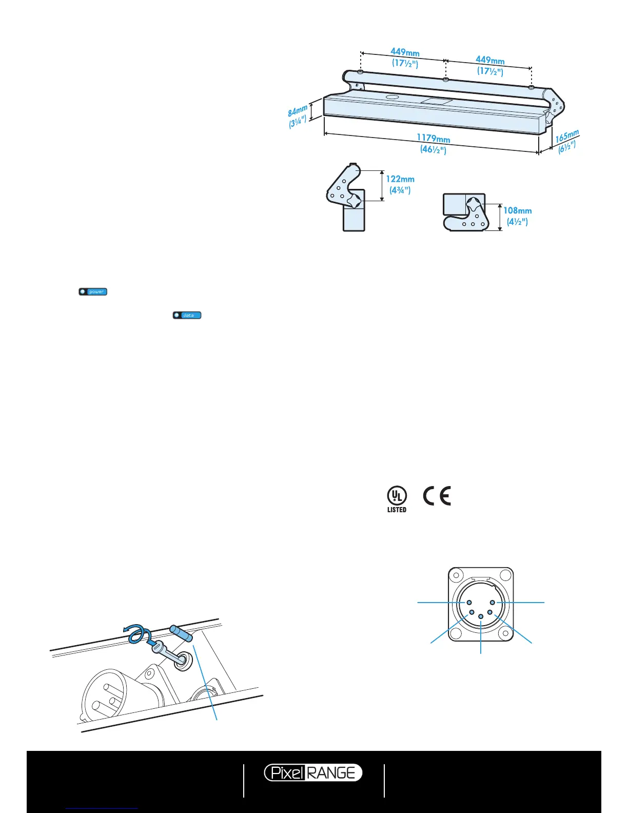
Specifications
Dimensions
Fuse type: 20mm 2A (T2AH)
anti-surge, ceramic body
PIN 1
Ground
PIN 2
Data
–
PIN 3
Data +
PIN 5
Not used
PIN 4
Not used
Documentation by Corporate Text & Design (www.ctxd.com)
Release 1.07b (original panel)
Using master mode to drive other units
This unit can control any number of other Pixel Range fix-
tures via DMX links, without the need for a control desk.
1 Set this unit as
master (PERS > DATA > MAST) and
ensure all others are set to
slave (PERS > DATA >
SLAV). Connect all fixtures via DMX daisy-chain.
2 Set each slave to
Mode > DMX.
3 Set each slave DMX address (using
ADDR > DMX) ac-
cording to the following:
18 cells are output in groups of 3 DMX channels to give
RGB values per cell (54 channels in total). Set the ad
-
dress of each slave fixture according to which of the 18
cells you want them to appear within, or to begin with
(for multi-cell fixtures): (A001 for cell 1, A004 for cell 2,
...
A052 for cell 18). Set RGBA slave fixtures to 3 chan-
nel mode (using
PERS > RES > 3ch).
4 Set the master to
Mode > EF m (the master unit’s DMX
address is ignored). On the master, choose the required
effects to display and send to the slave fixtures using
PROG > C1 and C2.
Weight
Fixture alone: 11kg (24 lbs)
With combi yoke: 12.2kg (26.9 lbs)
Power
Input voltage: 90 to 264V AC, 47 to 63Hz autosensing
Earth leakage 0.22mA
Connectors: 16 amp CEE Form 2Pole+Earth (input & output)
Power requirements: @ 230V/50Hz @ 115V/60Hz
Standby 20 watts 20 watts
Maximum (const.) 140 watts 140 watts
Start up (peak*) 32 amps 16 amps
* The peak value occurs only at first power up and
lasts only for a period measured in microseconds.
Adjustments may need to be made to supply circuit
breakers when multiple fixtures are daisy-chained,
causing them all to draw the peak simultaneously.
Approvals
Miscellaneous
Enclosure rating: IP20 (not protected against moisture ingress)
Control input: USITT DMX512 (input connector pin out below)
 Loading...