EasyManua.ls Logo

pizzato CS MP302 0 Series - User Manual

pizzato CS MP302 0 Series
18 pages
Go to English
Print Icon
To Next Page IconTo Next Page
Loading...
Pizzato Elettrica Srl
via Torino, 1
36063 MAROSTICA (VI)
ITALY
e-mail: info@pizzato.com
web site: www.pizzato.com
Phone: +39.0424.470.930
ZE FOG81B22-EU
1/18
1 INFORMAZIONI SUL PRESENTE DOCUMENTO
1.1 Funzione
Le presenti istruzioni per l’uso forniscono informazioni su installazione, collegamento
e uso sicuro dei seguenti articoli: CSMP302•0.
1.2 A chi si rivolge
Le operazioni descritte nelle presenti istruzioni per l’uso devono essere eseguite
esclusivamente da personale qualificato, perfettamente in grado di comprenderle, con
le necessarie qualifiche tecnico professionali per intervenire sulle macchine e impianti
in cui saranno installati i dispositivi di sicurezza.
1.3 Campo di applicazione
Le presenti istruzioni si applicano esclusivamente ai prodotti elencati nel paragrafo
Funzione e ai loro accessori.
1.4 Istruzioni originali
La versione in lingua italiana rappresenta le istruzioni originali del dispositivo. Le ver-
sioni disponibili nelle altre lingue sono una traduzione delle istruzioni originali.
2 SIMBOLOGIA UTILIZZATA
Questo simbolo segnala valide informazioni supplementari
Attenzione: Il mancato rispetto di questa nota di attenzione può causare rotture
o malfunzionamenti, con possibile perdita della funzione di sicurezza.
3 DESCRIZIONE
3.1 Descrizione del dispositivo
Il dispositivo di sicurezza descritto nel presente manuale è definito in accordo alla
Direttiva Macchine 2006/42/CE come blocco logico per funzioni di sicurezza.
Questo modulo di sicurezza multifunzione viene usato per implementare funzioni di
sicurezza come ad esempio il monitoraggio di arresti di emergenza, controllo porte o
ripari, monitoraggio di barriere di sicurezza, tappeti di sicurezza o sensori magnetici
presenti nei macchinari industriali. Questo dispositivo è particolarmente indicato per
controllare macchinari che richiedono svariate funzioni di sicurezza combinate tra di
loro (ad esempio controllo dell’arresto di emergenza e contemporaneamente controllo
protezioni), oppure macchinari che hanno parti che devono essere isolate durante il
normale funzionamento (ad esempio per manutenzione).
3.2 Funzioni del dispositivo
Questo modulo di sicurezza multifunzione è dotato di molteplici ingressi, che vengono
valutati da un programma applicativo per attivare le uscite di sicurezza o di segnala-
zione. Per raggiungere i più elevati livelli di sicurezza questo dispositivo ha una strut-
tura ridondante ed autocontrollata con due processori che verificano in continuazione
ed in modo coordinato il sistema. Il modulo presenta inoltre numerosi LED verdi per
rappresentare lo stato degli ingressi e delle uscite e due LED rosso/blu (P1, P2) per
evidenziare lo stato dei processori o eventuali guasti.
Lo stato sicuro corrisponde allo spegnimento delle uscite sicure (safe power off).
La funzione di sicurezza realizzata dal modulo è costruita e configurata usando i
blocchi logici disponibili nel software di configurazione Gemnis Studio, distribuito da
Pizzato Elettrica con licenza gratuita, che deve essere installato su un PC esterno.
Una funzione di sicurezza generale può essere definita come segue:
- le uscite sicure sono spente entro il tempo di reazione dichiarato se l’esito del riso-
lutore logico programmabile (programma applicativo) è negativo o sono presenti
errori.
In funzione delle caratteristiche dei dispositivi esterni e della struttura circuitale con
questo modulo è possibile ottenere circuiti di sicurezza fino a:
- SIL 3 secondo EN 62061;
- PLe secondo EN ISO 13849-1;
- categoria di sicurezza 4 secondo EN ISO 13849-1.
3.3 Uso previsto del dispositivo
- Il dispositivo descritto nelle presenti istruzioni per l’uso nasce per essere applicato
su macchine industriali.
- È vietata la vendita diretta al pubblico di questo dispositivo. L’uso e l’installazione
sono riservati a personale specializzato.
- Non è consentito utilizzare il dispositivo per usi diversi da quanto indicato nelle pre-
senti istruzioni per l’uso.
- Ogni utilizzo non espressamente previsto nelle presenti istruzioni per l’uso è da
considerarsi come utilizzo non previsto da parte del costruttore.
- Sono inoltre da considerare utilizzi non previsti:
a) utilizzo del dispositivo a cui siano state apportate modifiche strutturali, tecniche o
elettriche;
b) utilizzo del prodotto in un campo di applicazione diverso da quanto riportato nel
paragrafo CARATTERISTICHE TECNICHE.
4 FUNZIONAMENTO
4.1 Definizioni
- Programma applicativo: la parte del software interno del modulo di sicurezza che è
orientata all’applicazione del cliente.
- POWER ON: lo stato del modulo di sicurezza che dura dal momento dell’accensione
fino alla fine dei controlli interni.
- RUN: lo stato del modulo di sicurezza dopo la fine della fase di POWER ON (se non
sono stati rilevati errori) nel quale viene eseguito il programma applicativo.
- ERROR: lo stato del modulo di sicurezza quando viene rilevato un guasto. In questo
stato il modulo si pone in condizioni di sicurezza ossia con tutte le uscite di sicu-
rezza disattivate.
- Guasto: un guasto può essere interno o esterno al modulo di sicurezza. I guasti
interni sono rilevati autonomamente dal modulo grazie alla sua struttura ridondante
ed autocontrollata. Un guasto esterno al modulo può essere rilevato dal programma
applicativo. Ne consegue che la definizione di guasto esterno è strettamente dipen-
dente dall’applicazione (vedi nota A).
4.2 Descrizione funzionamento
Quando viene data alimentazione il modulo entra in stato di POWER ON ed effettua
una autodiagnosi interna. In questa fase i due led (P1, P2) dei processori rimangono
accesi con luce rossa per circa 1 secondo. Se i test interni terminano senza anomalie
i due led si spengono ed il modulo entra in stato di RUN ed esegue il programma ap-
plicativo. Se i test di avvio non vengono superati il modulo entra in stato di ERROR ed
i led dei processori (P1, P2) segnalano l’anomalia rimanendo accesi con luce rossa.
I led verdi relativi all’alimentazione e gli ingressi del modulo non sono controllati dai
processori ed iniziano immediatamente ad indicare lo stato dei relativi ingressi/uscite.
Quando il modulo è nello stato di RUN e non vengono rilevati guasti i due led (P1, P2)
rimangono spenti.
In stato di RUN il modulo può rilevare dei guasti esterni al modulo, ad esempio a cau-
sa di cortocircuiti o stati invalidi degli ingressi (vedi nota A). A seconda della tipologia
di guasto rilevato il programma applicativo può imporre al modulo di porsi in stato
di ERROR per evidenziare l’anomalia. In questo caso il programma applicativo può
comunicare un codice di errore mediante una sequenza di lampeggi dei led (P1, P2).
Durante lo stato di RUN, in parallelo all’esecuzione del programma applicativo, il mo-
dulo effettua costantemente una serie di test interni per verificare il corretto funzio-
namento dell’hardware. Se viene rilevata una anomalia il modulo passa in stato di
ERROR.
Quando è in stato di ERROR il modulo si pone in condizioni di sicurezza ossia con
tutte le uscite di sicurezza aperte, il programma applicativo non viene più valutato
e così gli ingressi del sistema. Inoltre le uscite statiche di segnalazione rimangono
invariate (i cambiamenti negli ingressi non le influenzano) al valore imposto dal pro-
gramma applicativo prima di entrare nello stato di ERROR. Per resettare il modulo è
necessario spegnerlo per un tempo sufficiente (vedi dati tecnici) e quindi riaccenderlo.
Nota A: Un cortocircuito non è sempre un guasto. Per esempio in un normale pulsante per arresti
di emergenza dotato di due contatti NC l’apertura dei contatti è il segnale che deve essere valutato
ed un cortocircuito tra i due contatti è un guasto. Invece in un tappeto di sicurezza con tecnologia a
4 fili la situazione è opposta e un cortocircuito tra i fili è il segnale che deve essere valutato mentre
l’interruzione dei fili è un guasto.
4.3 Aumento di numero e portata dei contatti
Nel caso ci fosse la necessità è possibile aumentare il numero e la portata dei contatti
di uscita con l’ausilio di contattori esterni con contatti a guida forzata
Circuito di retroazione per contattori esterni
con start automatico
Circuito di retroazione per contattori esterni
con start manuale o controllato
K8
K7
K7
K8
F
-
+
Tx
Ix 24 Vdc
OS1
OS2
K8
K7
K7
K8
F
-
+
Tx
Ix 24 Vdc
OS1
OS2
Per un corretto funzionamento eventuali moduli o PLC connessi alle uscite sicure
elettroniche OSx devono tollerare i test ciclici di disattivazione che vengono effettuati
sulle medesime.
5 SCHEMA INTERNO
P1
P2
T02
...
T24
T01
I12
...
I48
I11
A1
OS2
OS1
OS3
A2
O02
...
O04
O01
OS4
24V
6 SEGNALAZIONI
Led PWR Led P1, P2 Possibile causa di guasto
Off Off
Mancanza di alimentazione, connessioni errate, fili di alimentazione tagliati,
rottura di fusibili esterni.
Guasto del modulo.
Question and Answer IconNeed help?

Do you have a question about the pizzato CS MP302 0 Series and is the answer not in the manual?

Overview

This document describes the Pizzato Elettrica CS MP302-0, a multifunction safety module designed for industrial machinery.

Function Description

The CS MP302-0 is defined as a logic block for safety functions according to Machinery Directive 2006/42/CE. It's used to implement safety functions such as emergency stop monitoring, door or guard control, safety barrier monitoring, safety mats, or magnetic sensors in industrial machinery. This device is particularly suitable for controlling machinery that requires various combined safety functions (e.g., emergency stop control and simultaneous protection control), or machinery with parts that need to be isolated during normal operation (e.g., for maintenance).

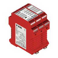
The module features multiple inputs evaluated by an application program to activate safety or signaling outputs. To achieve the highest safety levels, it has a redundant and self-controlled structure with two processors that continuously and coordinately verify the system. The module also has numerous green LEDs to indicate the status of inputs and outputs, and two red/blue LEDs (P1, P2) to indicate the status of the processors or any faults. The safe state corresponds to the deactivation of the safe outputs (safe power off).

The safety function implemented by the module is built and configured using the logic blocks available in the Gemnis Studio configuration software, distributed by Pizzato Elettrica with a free license. A general safety function can be defined as follows: the safe outputs are deactivated within the declared reaction time if the result of the programmable logic solver (application program) is negative or if errors are present. Depending on the characteristics of external devices and the circuit structure, this module can achieve safety circuits up to: SIL 3 according to EN 62061; PL e according to EN ISO 13849-1; safety category 4 according to EN ISO 13849-1.

When power is supplied, the module enters the POWER ON state and performs an internal self-diagnosis. During this phase, the two processor LEDs (P1, P2) remain lit red for approximately 1 second. If the internal tests complete without anomalies, the two LEDs turn off, and the module enters the RUN state and executes the application program. If the startup tests are not successfully completed, the module enters the ERROR state, and the processor LEDs (P1, P2) indicate the anomaly by remaining lit red. The green LEDs for power supply and module inputs are not controlled by the processors and immediately indicate the status of the respective inputs/outputs. When the module is in the RUN state and no faults are detected, the two LEDs (P1, P2) remain off.

In the RUN state, the module can detect external faults, for example, due to short circuits or invalid input states. Depending on the type of fault detected, the application program can force the module into the ERROR state to highlight the anomaly. In this case, the application program can communicate an error code via a blinking sequence of the LEDs (P1, P2). During the RUN state, in parallel with the execution of the application program, the module continuously performs a series of internal tests to verify the correct functioning of the hardware. If an anomaly is detected, the module enters the ERROR state.

When in the ERROR state, the module enters a safe condition, meaning all safety outputs are open, the application program is no longer evaluated, and the system inputs are not affected. Additionally, the static signaling outputs remain unchanged (input changes do not affect them) at the value set by the application program before entering the ERROR state. To reset the module, it must be powered off for a sufficient time (see technical data) and then powered back on.

Important Technical Specifications

Housing:

  • Material: Polyamide PA 66, self-extinguishing V0 according to UL 94
  • Protection degree: IP40 (housing), IP20 (terminal strip)
  • Cable cross section: 0.2 ... 2.5 mm² (24 ... 12 AWG)
  • Terminal tightening torque: 0.5 ... 0.6 Nm
  • Installation on: 35x7.5 DIN rail (EN 60715)

General Data:

  • SIL: Up to SIL 3 according to EN 62061
  • Performance Level (PL): Up to PL e according to EN ISO 13849-1:2015
  • Safety category: Up to cat. 4 according to EN ISO 13849-1:2015
  • MTTFD: 535 years
  • DC: High
  • PFHD: 1.57 E-09
  • Mission time: 20 years
  • System response time: < 30 ms
  • Ambient temperature: 0°C ... +55°C
  • Storage temperature: -20°C ... +70°C
  • Mechanical endurance: > 10 million operating cycles
  • Electrical endurance: > 100,000 operating cycles
  • Pollution degree: external 3, internal 2
  • Overvoltage category: II
  • Air and surface distances: according to EN 60947-1

Power Supply (A1-A2):

  • Rated supply voltage U: 24 Vdc
  • Supply voltage tolerance: ±15% of U
  • Max. residual ripple: 10%
  • Rated consumption (w/o load): <3 W
  • Internal general protection: PTC, Ih=1.5 A
  • PTC response time: response time > 100 ms, release time > 3 s
  • Internal protection against short circuits on outputs (Tx, Ox): electronic
  • Maximum current output of the module as the total current of the Ox and Tx outputs: 0.5 A
  • Self-test duration on startup: < 2 s

Input Circuits (Ix):

  • Number of inputs: 24
  • Voltage and current in the input circuits: 24 V, 5 mA
  • Input signals: 0-8 V (Off), 12-24 V (On)
  • Galvanic separation: no
  • Minimum duration of input signal: 10 ms
  • Input signal filtering: yes, maximum interference period 0.4 ms
  • Maximum input resistance: 100 Ω
  • Maximum input capacitance: 470 nF to ground, 470 nF between two conductors

Circuits with Test Signals (Tx):

  • Number of test signals: 12
  • Signal type: pulsed 100 Hz 24V/0V, duty cycle 50%
  • Max. current per test signal: 0.2 A
  • Max. total current: See Power supply (A1-A2)
  • Protected against short circuit: yes
  • Galvanic separation: no

Semiconductor Signaling Output Circuits (Ox):

  • Number of outputs: 4
  • Output type: PNP
  • Maximum current per output: 0.5 A
  • Max. total current: See Power supply (A1-A2)
  • Impulse withstand voltage (Uimp): 0.8 kV
  • Rated insulation voltage (U): 32 V
  • Protected against short circuit: yes
  • Galvanic separation: no

Semiconductor Safety Output Circuits (OSx):

  • Number of outputs: 4
  • Rated voltage 24V-0V: 24 Vdc
  • Output type: PNP
  • Maximum current per output: 0.5 A
  • Max. total output current: 2 A
  • Minimum current: 10 mA
  • Maximum capacitive load to ground per output: 400 nF
  • Maximum inductive load per output: 500 mH
  • Protection fuse: 2 A type gG
  • Galvanic separation: Yes
  • Impulse withstand voltage (Uimp): 0.8 kV
  • Rated insulation voltage (U): 32 V
  • Short circuit detection between outputs: Yes
  • Duration of the deactivation impulses at the safety outputs: < 300 µs

Usage Features

The device is intended for use in industrial machinery. Direct public sale is prohibited; use and installation are reserved for specialized personnel. It is not permitted to use the device for purposes other than those indicated in these instructions. Any use not expressly provided for in these instructions is considered unintended by the manufacturer. Unintended uses also include:

  • Use of the device with structural, technical, or electrical modifications.
  • Use of the product in an application field different from that specified in the TECHNICAL DATA section.

The number and capacity of output contacts can be increased using external contactors with forcibly guided contacts. For correct operation, any modules or PLCs connected to the electronic safety outputs (OSx) must tolerate the cyclic deactivation tests performed on them.

The device must be installed only inside a cabinet with a protection degree not less than IP54 according to EN 60529. It must always be affixed with the specific DIN rail adapter according to EN 60715. Avoid stressing the device with bending or torsion. Do not modify or open the device for any reason. The device carries out an operator protection function; any inadequate installation or tampering can cause serious injuries, property damage, and economic losses. These devices must not be bypassed, removed, or disabled in any other way. If the machine where the device is installed is used for a purpose other than that specified, the device may not provide efficient operator protection. The safety category of the system (according to EN ISO 13849-1), including the safety device, also depends on the external components connected to it and their type.

The device should not be used in environments where:

  • Continual changes in temperature cause condensation inside the device.
  • The application causes the device to be subjected to strong impacts or vibrations.
  • Explosive or flammable gases or dusts are present.
  • Strongly aggressive chemicals are present, which may impair its physical or functional integrity.

Maintenance Features

Do not disassemble or attempt to repair the device. In case of any malfunction or failure, replace the entire device. The device installer is responsible for establishing the sequence of functional tests to which the device is to be subjected before the machine is started up and during maintenance intervals. The sequence of functional tests can vary depending on the machine complexity and circuit diagram; therefore, the sequence detailed below is considered minimal and not exhaustive.

Perform the following sequence of checks before the machine is commissioned and at least once a year (or after a prolonged shutdown):

  1. Check that the safety module housing is undamaged and in good condition. If the housing is damaged, replace the entire device.
  2. Check that all signaling LEDs are working.
  3. Check that the electrical cables are firmly lodged inside the terminals and connectors.
  4. Check that the module functions as required by the application program.

The device is designed for applications in dangerous environments and therefore has a limited service life. Although still functioning, the device must be completely replaced 20 years from the date of manufacture. The date of manufacture is placed next to the product code.

Do not install the safety module if voltage is present. Power the device only when the electrical circuits have been completely realized according to the specifications indicated in the OPERATION paragraph. The first time you start the machine, ensure that there are no people close to hazardous areas. Check that the supply voltage is correct before powering the device. Keep the charge within the values specified in the electrical operation categories. Only connect and disconnect the device when the power is off. When using plug-in-type terminal blocks, they may only be plugged in or unplugged if no supply voltage is present. Discharge static electricity before handling the product by touching a metal mass connected to earth. Any strong electrostatic discharge could damage the device. Power the safety module and the other devices connected to it from a single SELV/PELV source and in accordance with the applicable standards (applies only to versions with a supply voltage of 12 V and 24 V). Plug-in type connectors, and in particular those of the output contacts of relays (when installed) may be powered by high voltage. We recommend keeping the power supply of the safety module galvanically separated from the power section of the machine and keeping the connection cables of the module separated from the power cables. Always connect the protection fuse (or equivalent device) in series with the power supply for each device. Always connect the protection fuse (or equivalent device) in series to the safety electrical contacts. During and after the installation, do not pull the electrical cables connected to the device. If excessive tension is applied to the cables, the device may be damaged.

pizzato CS MP302 0 Series Specifications

General IconGeneral
Brandpizzato
ModelCS MP302 0 Series
CategorySafety Equipment
LanguageEnglish

Related product manuals