C S 3
22
INTRODUCTION
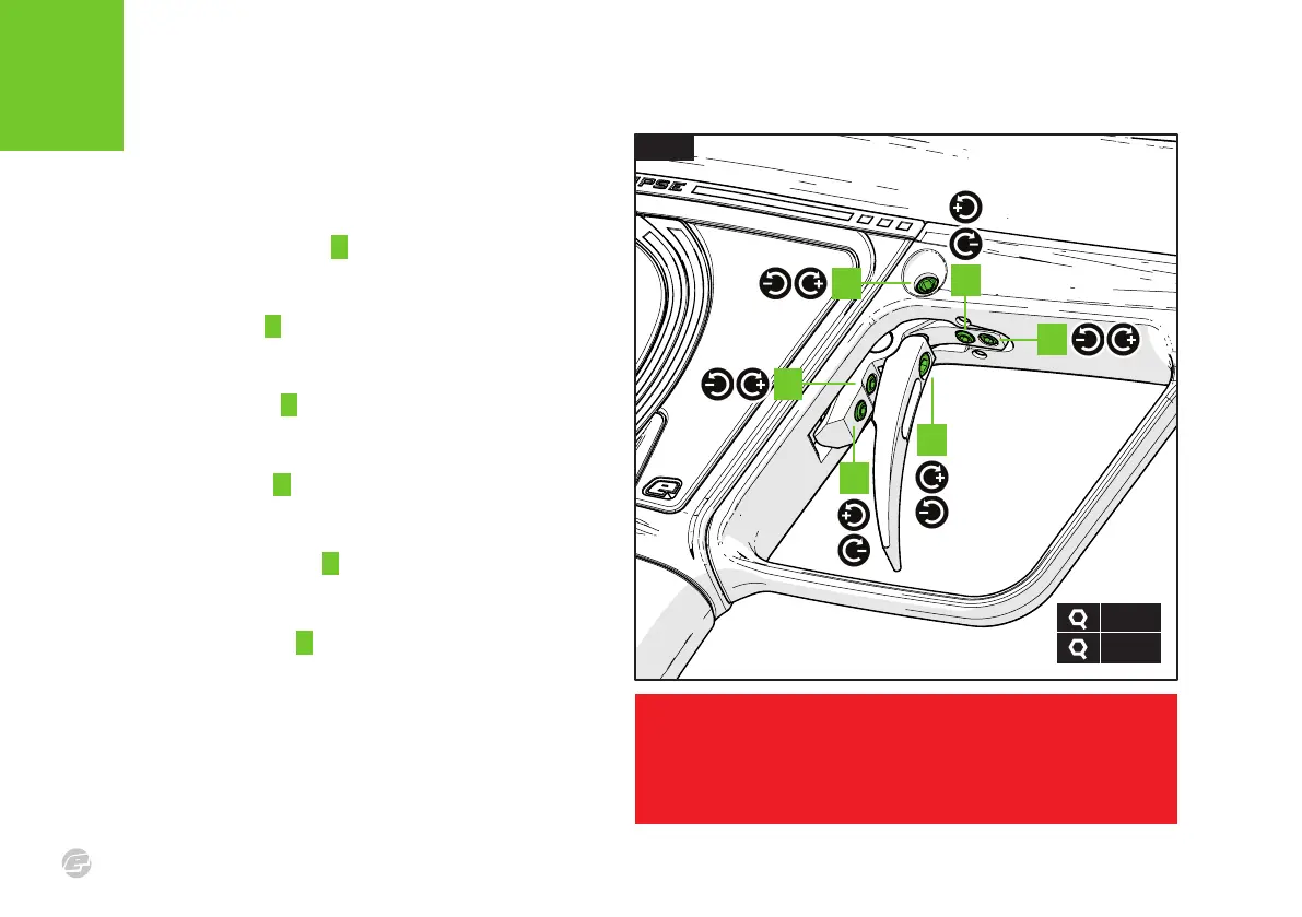
TR IGGE R A DJU STMEN T
FIG.1
The rake adjustment screw (5/64) A controls the angle of the trigger
shoe. Rotate the screw counter-clockwise to loosen the shoe for
manual adjustment. Clockwise to secure the shoe in place.
Spring return screw (1/16) B adjusts the spring strength of the trigger
return. Clockwise increases the strength, counter-clockwise
decreases it.
The (1/16) post-travel screw C adjusts the distance the trigger travels
once pulled. Clockwise reduces the amount of travel (shortening the
trigger) counter-clockwise increases the trigger pull distance.
The (1/16) pre-travel screw D adjusts the distance the trigger travels
before being pulled. Clockwise reduces the amount of travel
(shortening the trigger), counter-clockwise increases the distance.
The (1/16) magnet adjuster screw E adjusts the strength of the
trigger return. Clockwise increases the strength, counter-clockwise
reduces it.
Trigger retaining screw (5/64) F holds the trigger assembly in place.
Removing this allows the assembly to be removed via trigger guard.
Counter-clockwise to remove the screw, clockwise to secure.
WARNING!
DO NOT wind the screws in too far as this may prevent the marker from firing, or even
damage it. If pre-travel screw is wound in too far the marker may fire unintentionally.
C
A
D
FIG .1
1/16”
5/64”
F
B
E