Do you have a question about the Plasmatronics PL20 and is the answer not in the manual?
Describes the Boost stage of battery charging, where full current is used.
Explains optional equalisation for battery health, balancing cell voltages.
Details the Absorption state, maintaining constant voltage to complete charging.
Covers the Float state, maintaining full charge with minimal current.
Manages generator start/stop signals for automatic backup power systems.
Periodically exercises the generator to prevent seizing, ensuring operational readiness.
Configures a delay to prevent transient loads from triggering generator state changes.
Prevents battery damage by automatically disconnecting loads when voltage is too low.
Displays maximum and minimum battery voltages recorded since midnight.
Shows the time the regulator entered the Float state after a full charge cycle.
Estimates battery fullness based on amp-hour balance, requiring accurate system monitoring.
Displays battery temperature and allows setting lockout to prevent tampering.
Shows the solar panel voltage when the circuit is open, temporarily disabling charge.
Records daily performance data (IN, OUT, VMAX, etc.) for up to 30 days.
Sets the system time in 24-hour format, affecting history logging and event control.
Configures the nominal system voltage, determining regulation and control set-points.
Selects preconfigured programs or customizes settings via Program 4.
Adjusts specific voltage and current regulation parameters for custom configurations.
Configures various operational settings like terminal functions, PWM, and alarm voltage.
Manages dump loads for wind/hydro generators, diverting excess energy to maintain battery voltage.
Configures the B- sense input for battery negative voltage sensing or event triggering.
Sets up conditional events for automating tasks based on system parameters.
Lists and describes optional accessories like shunt adaptors, sensors, and interface cables.
Provides detailed electrical and physical specifications for the PL series controllers.
Specifies recommended catch diodes for various terminals to prevent voltage spikes.
Illustrates the internal hardware architecture and component connections for PL20/40 models.
Shows the internal hardware architecture and component connections for PL60/80 models.
Details how high ambient temperatures reduce current ratings to prevent overheating.
Visual representation of menu structures and settings flow for system configuration.
Provides a logbook template for recording daily performance metrics and comments.
Outlines the menu structure and navigation for pre-configured battery programs 0-3.
Details the menu navigation for custom configuration using Program 4.
Provides physical dimensions, lid material, and weight specifications for PL series controllers.
| Manufacturer | Plasmatronics |
|---|---|
| Product Category | Solar Charge Controller |
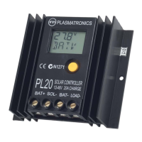
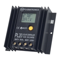
| Model | PL20 |
| Maximum PV Input Voltage | 50 V |
| Maximum Output Current | 20 A |
| Temperature Compensation | -5 mV/°C/cell |
| Input Voltage | 12V / 24V |
| Battery Voltage | 12V / 24V |
| Battery Type | Gel, AGM |
| Protection | Overload, Short Circuit, Reverse Polarity, Over Temperature |
| Load Disconnect Voltage | Adjustable |
| Load Reconnect Voltage | Adjustable |