Rev 6.3.0 12.09.16
PL Reference Manual
11
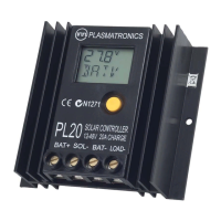
NC
NO
Battery Positive
+
PL60/PL80 Generator start relay wiring
PL60/80
SOL-
BAT-
BAT+
SOL+
Load+
Load-
G Contacts
(300mA max)
-
Battery Negative
}
To Generator
Start input
Optional Series Resistor:
A series resistor can be
used to drop the voltage
across the relay to lower
than the battery voltage.
You need to calculate
resistor value/power.
Fig. 2C - PL60/PL80 Generator
start relay wiring
Catch
Diode
must
be
tted
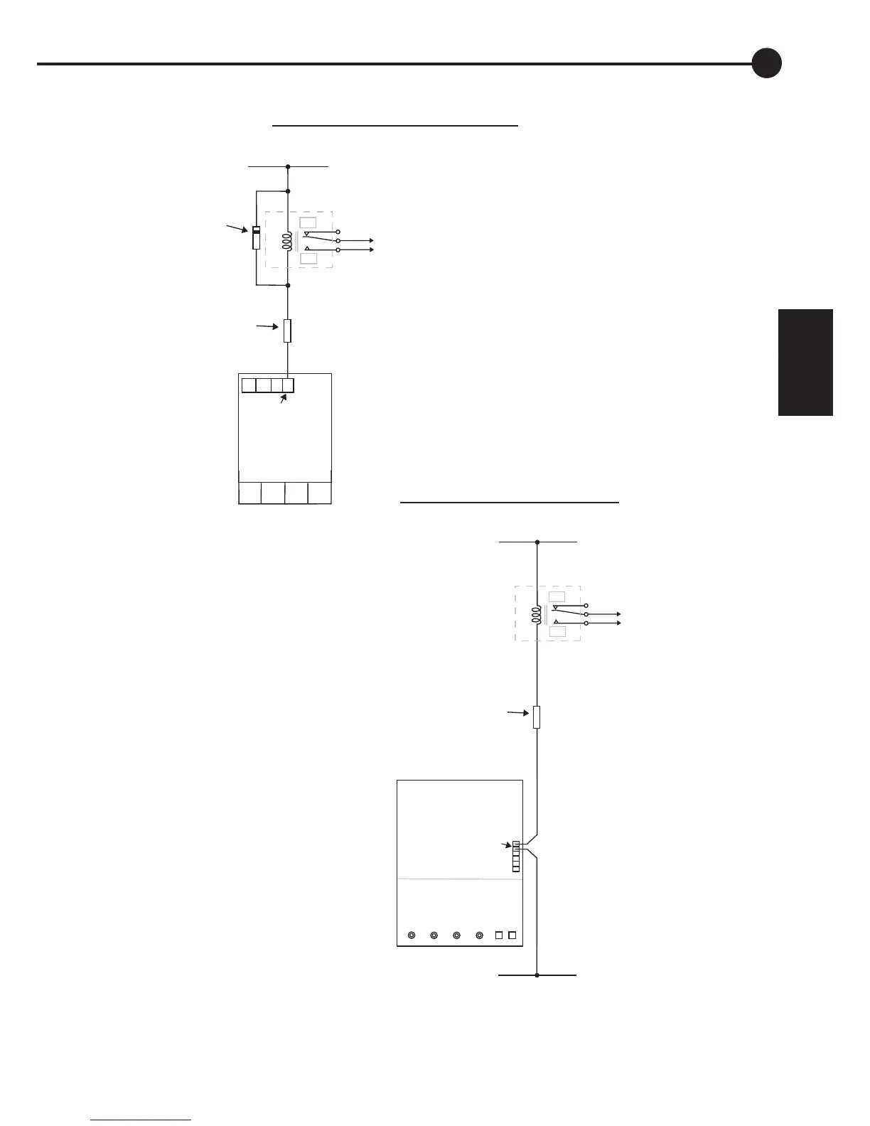
NC
NO
Battery Positive
+
PL20/40 Generator start relay wiring
PL20/40
-
Relay
}
To Generator
Hint:
Note:
Start input
(Typically contact closure
starts generator, but
consult generator manual)
The relay can be replaced
with a suitable visual
indicator (LED + resistor
or a small lamp) to show
the user when to start the
generator.
Max current = 120mA
(Typically contact closure
starts generator, but
consult generator manual)
Since the ‘G Contacts’ are
voltage-free, the relay can
be switched in the negative
or positive wire (negative
wire switching shown)
Many installations won’t require
an external relay and can be
switched directly from the ‘G’
outputs (max current 300mA).
Use an external relay if unsure.
B+ S- B- L-
B- T+ T- G
120mA max
Optional Series Resistor:
A series resistor can be
used to drop the voltage
across the relay to lower
than the battery voltage.
You need to calculate
resistor value/power.
(eg 1N14007)
Fig. 2B - PL20/40 Generator
start relay wiring
2