15
TD-000368-01-A
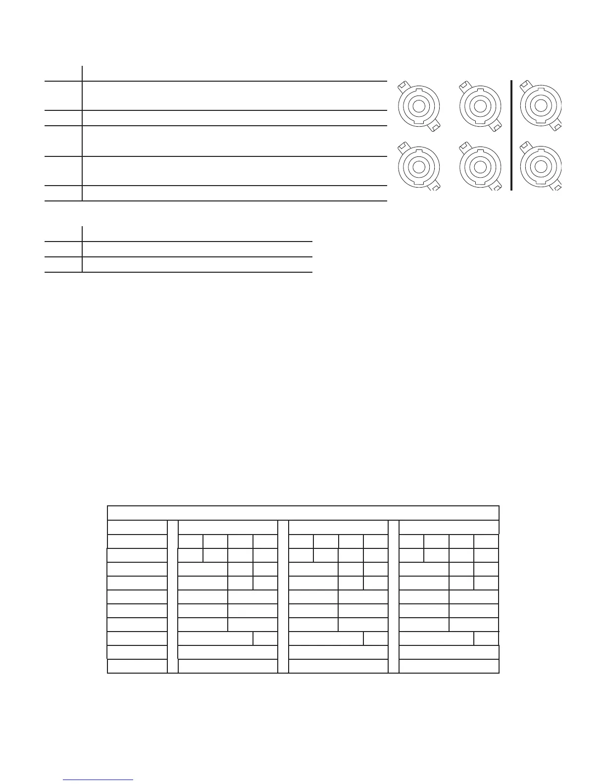
Mode
NL4 Separate AB Parallel ABC Parallel ABCD Parallel
A
Ch A 1+ / 1-
1+ / 1- 1+ / 1- 1+ / 1-
Ch B 2+ / 2-
1
B
1+ / 1- 1+ / 1- 1+ / 1- 1+ / 1-
CD Parallel
C
Ch C 1+ / 1-
1+ / 1- 1+ / 1- 1+ / 1-
Ch D 2+ / 2-
1
D
1+ / 1- 1+ / 1- 1+ / 1-
A+B Bridged C+D Bridged AB+CD Bridged
X
1+ / 1- 2+ / 2-
1
1+ / 1-
Y
1+ / 1-
— Table 1 —
1 For Bi-Amp operation.
AC Power On
After connecting the outputs to the loudspeakers, you may turn the amplifi er on.
1. Make sure the output gain settings for all audio-source devices (CD Players, Mixers, Instruments, etc.) at the lowest output (max attenuation).
2. Turn on all audio sources.
3. Turn the AC Mains power switch on the back of the amplifi er to ON. The amplifi er starts in the state it was in when power was removed.
4. You can now bring up the outputs of your audio sources.
Power Distribution Charts
The following charts show the maximum power output for each channel in each confi guration, and under different loads.
PLD 4.3 — Total Power: 2500W
8 Load 4 Load 2 Load
Confi guration
ABCD ABCD ABCD
4 CH (A B C D) 625 625 625 625 650 650 650 650 600 600 600 600
3 CH (AB C D) 1000 625 625 1200 650 650 1200 600 600
3 CH (A+B C D) 1250 625 625 1150 650 650 625 600 600
2 CH (AB CD) 1000 1000 1200 1200 1200 1200
2 CH (AB C+D) 1000 1250 1200 1150 1200 625
2 CH (A+B C+D) 1250 1250 1150 1150 625 625
2 CH Alt (ABC D) 1100 625 2000 650 2500 600
1 CH (ABCD) 1100 2100 2500
1 CH (AB+CD) 2500 2370 2230
— Table 2 —
— Figure 24 —
A
C
B
D
X
Y
Standard Bridged
Output Connectors