2.3 Installing the hydraulic motor
WARNINGS
1 A COMPETENT TECHNICIAN MUST CARRY OUT THIS DESIGN AND INSTALLATION.
2 THE PRESSURE RELIEF VALVE SETS THE MAXIMUM REWIND POWER OF THE
HOSEREEL. THIS LEVEL MUST BE SET LOW ENOUGH TO PROTECT THE
OPERATOR.
2.3.1 All hydraulic rewind hosereels must be connected to a suitable hydraulic control system. In the Collins
Youldon hydraulic control system there are three main components. These are a changeover valve, a
flow control valve and a three position control lever with pressure relief valve. The function of these
components are described below and figure 5 shows a suggested layout for the complete system.
(i) Changeover valve – directs hydraulic power either to the hosereel or cargo pump.
(ii) Flow control valve – enables the maximum rewind speed to be pre-set during installation by
adjustment of the flow of hydraulic oil to the motor.
(iii) Combined three-position control lever and pressure relief valve – controls the operation of the
reel. The control positions and their functions are:
Position 2 – allows the reel to freewheel when the hose is being deployed but without over-
running. Note: The handwheel friction brake provides additional friction braking, see section
2.4.
Position 0 – locks the reel so that the hose is discouraged from shaking loose during transit.
Position 1 – energises the hydraulic motor and rewinds the hose. The lever will detent into
positions 0 and 2. There is a spring return from position 1 to position 0.
Pressure relief valve – sets the maximum rewind power of the hosereel, and must be set during
installation to give a safe maximum rewind torque
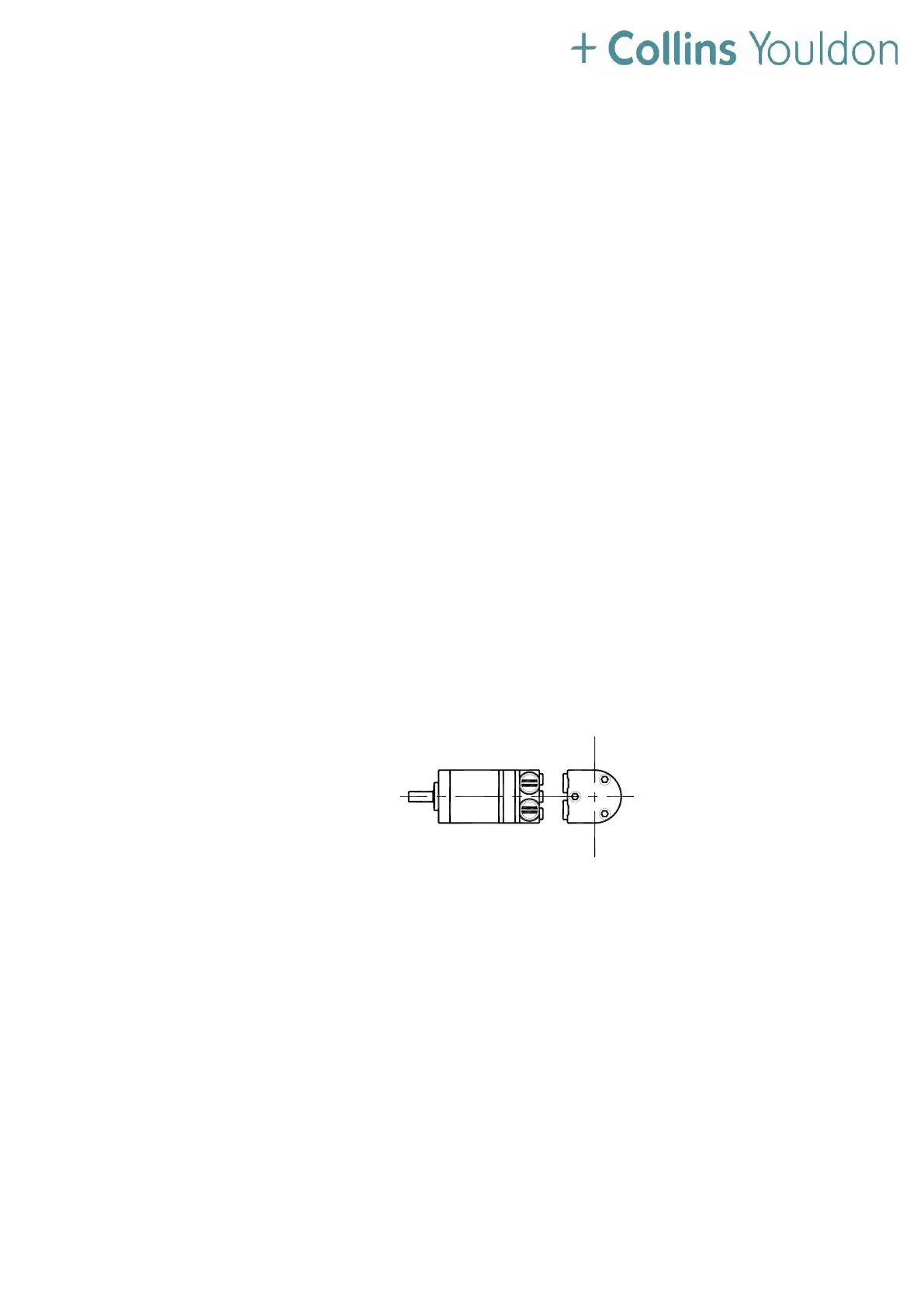
Figure 3 – Hydraulic motor
 Loading...