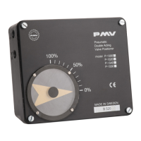
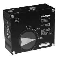
The PMV P-1500 and P-1700 series are valve positioners designed for accurate and reliable control of pneumatic actuators. These devices operate on the principle of balanced forces, ensuring precise positioning of a valve based on a signal pressure. The P-1500 and P-1700 positioners are intended for installation in machine/application systems and are manufactured in compliance with EC directive 89/392/EEC. Commissioning is strictly prohibited until the entire machine/application also complies with this directive.
Function Description
The core function of the PMV positioner is to translate a signal pressure into a corresponding mechanical position of a valve. This is achieved through a balanced force system. One force is generated by the signal pressure acting on bellows (25), which in turn influences a balance arm (19). The opposing force comes from a feedback spring (14), which is proportional to the level of a lower arm (8).
The lower arm's position is determined by a cam (6) secured to a spindle (2). This spindle is activated by the cylinder rod of the actuator. When the forces exerted by the bellows and the feedback spring are equal, the balance arm (19) assumes a central, neutral position. Consequently, the spool (30) also remains in a neutral state.
A slight leakage of air occurs past the close tolerances between the pilot valve parts (29 and 30). This allows a small flow of air from the supply (S) through the pilot valve ports into the cylinder via connections C1 and C2. Another small amount of air leaks into the positioner housing.
Equilibrium Position and Response to Signal Change:
In an equilibrium state, the valve is at a stable position corresponding to the current signal pressure. If the control pressure increases, the bellows (25) will deflect downwards, compressing the feedback spring (14). This movement of the balance arm (19) shifts the spool (30) within the valve body (29). This guides supply air to one side of the piston while simultaneously exhausting air from the other side through connection C1 into the positioner housing.
The cylinder piston then moves, rotating the spindle (2) and cam (6) clockwise. This action forces the lower arm (8) upwards, further compressing the feedback spring (14). These movements continue until the additional force from the feedback spring (14) on the balance arm (19) counteracts the increased force from the bellows (25). At this point, the balance arm (19) returns to its neutral position, and the spool (30) also returns to neutral. The cylinder position becomes stable at this new, adjusted position.
A key characteristic of this system is that there is only one stable cylinder position for each specific signal pressure value. If an external force acts on the cylinder piston rod, it will cause a momentary displacement. However, the interaction between the cam (6), lower arm (8), spring (14), balance arm (19), and spool (30) will generate a pressure difference within the cylinder that counter-balances the external force, bringing the system back to its set point.
Important Technical Specifications
- Supply Pressure: Up to 10 bar (150 psi).
- Air Quality: Requires dry, clean, oil-free air. A 25-micron filter should be installed as close as possible to the positioner. For large supply air pressure variations, a pressure regulator should be mounted between the filter and positioner to eliminate fluctuations.
- Connections:
- Supply air: Port S
- Control pressure: Port I
- Cylinder connections: Ports C1 and C2
- Bellows Length (P-1500/P-1700): Must be 35mm. Adjustment by stretching or compressing the bellows may be necessary during maintenance.
Usage Features
- Zero Adjustment: The positioner features an external zeroing screw for easy adjustment. This screw is equipped with a friction brake, eliminating the need for locking after adjustment.
- Control Pressure Range Adjustment: The effective length of the range spring can be varied by turning an adjusting nut at the top end of the spring. Increasing the effective length of the spring increases the actuator's travel for a fixed control range.
- Actuator Travel Adjustment:
- To Increase Travel: Back off the locking screw, turn the spring clockwise to increase its effective length, then tighten the screw. Re-zeroing is required after this adjustment. Large adjustments may necessitate repositioning the nut relative to the spring guide.
- To Reduce Travel: Back off the locking screw, turn the spring and top spring guide clockwise to allow space for the free end of the spring, thereby reducing the effective spring length. Re-zeroing is required.
- Action Change (Valve Opening/Closing): The positioner's action can be reversed (from valve opening on increasing signal to valve closing, or vice-versa). This involves:
- Shutting off supply and instrumental air.
- Reversing the flexible tubing between ports C1 and C2.
- Removing the positioner cover.
- Removing the nut fastening the cam to the spindle.
- Inverting the cam and positioning it to the desired signal range (stamped on the cam lobes).
- Reinstalling the nut (but not tightening it yet).
- Turning on supply and instrumental air.
- Ensuring the actuator is in the correct minimum signal position.
- Positioning the cam so the ball bearing does not ride on the inactive portion.
- Tightening the nut, allowing for slight clockwise rotation of the cam during tightening.
- Spring Guide Rotation: The top spring guide (18) can be turned through 120 degrees to ensure locking screws remain accessible. This is done by compressing the spring to release the guide from the balance arm, allowing rotation.
Maintenance Features
- Cleaning the Valve Body:
- Remove the four screws and the cover.
- Carefully remove the valve body, ensuring the spool slides easily and does not bind against the balance arm.
- Remove the screw retaining the intermediate piece.
- Wash components, blow them clean and dry with compressed air.
- Check ports C1 and C2 for cleanliness. Replace adapters with integrated filters if they cannot be cleaned.
- Check O-rings for good condition.
- Bellows Replacement:
- Remove the cover, spring, adjusting nut, and spring guide.
- Remove screws and the balance arm.
- Withdraw the bellows by turning it back and forth.
- Before fitting a new bellows, measure its length (must be 35mm) and adjust if necessary by stretching or compressing.
- Check the O-ring condition and take care when compressing the bellows into place.
- Refit the balance arm and spring.
- Indicator Zeroing:
- Remove the four screws and the cover.
- Back off the locking screw and zero the indicator.
- Replace the cover to check the setting; make fine adjustments if needed.
- Tighten the locking screw gently to avoid cracking the indicator.
- Mount the cover and tighten the four screws.
- Intermediate Piece Installation:
- Fit the intermediate piece and tighten the screw lightly.
- Ensure the bottom edge of the intermediate piece is slightly (0.5-1 mm) outside the casing face.
- Fit the valve body with the spool, taking care not to damage the groove for the balance arm.
- Fit screws with washers, press the valve body against the intermediate piece, back off the screw, press hard, and then tighten the screws.
- Adjust the starting point using the screw.
All adjustments require careful attention to ensure screws are securely fastened after completion. If screws are not accessible, the spring guide may need to be rotated.