Do you have a question about the PMV P-2000 and is the answer not in the manual?
Store units in original shipping containers in an environmentally controlled area, clean, cool, and dry.
Ensure air supply is on, seal enclosures, and protect from elements when storing outdoors.
Condensation can form in hot, humid climates, causing erratic operation or failure due to water or corrosion.
Input signal creates torque; feedback linkage creates counter-torque for balance.
Spring position on beam/balance arm adjusts positioner gain for actuator size.
Flip cam and interchange connections C1/C2 to change action; split range uses different cam curves.
Connect ports C1 and C2 to actuator; use appropriate feedback spindle designs.
Connect port S to instrument quality air supply (max 8 bar); use regulator if pressure varies.
Port I is for electrical connection gland (1/2" NPT or PG 13.5).
P-2000 Ex/P-2020 Ex must connect to intrinsically safe circuits; refer to installation drawing.
Orient the cam correctly before switching on supply air; adjust cam for correct orientation.
Flip the cam and interchange connections C1/C2 to change the action.
Adjust gain by moving the spring on the beam/balance arm to match actuator dynamics.
Move the gain spring to the left using tweezers; requires new zero adjustment.
Set input signal to 4 mA, adjust zero setting screw until actuator is in starting position.
Set input signal to 20 mA; adjust range screw to reduce/increase actuator travel.
Keep cover mounted to prevent iron dust entering the force coil gap.
Not required unless supply air quality is poor, causing iron dust ingress.
Located near supply air connection (S); removable for exchange. Check O-rings.
Unscrew cover, remove side frame, unscrew indicator, remove nut/cam, then valve body.
Remove cover, side frame, indicator, cam, valve body, and spool.
Handle with caution; spool and valve body are matched. Check for wear and smooth movement.
Check supply pressure, wiring, pipe connections, and cam usage.
Check pipe connections between positioner and actuator.
Check for dirty valve body, restrictor, nozzle, magnet gap, or defective diaphragms.
Check for high internal gain or restricted supply air capacity.
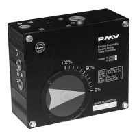
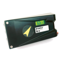
Electro-pneumatic valve positioner, controls actuator position using non-inflammable gas.
Lists temperature classifications (T4, T5, T6) based on short circuit current.
Details test documents, drawings, and PTB approval for intrinsic safety.
Notes on ambient temperature, single barrier leg use, and intrinsic safety components.
Notes on output voltage-current plot, installation guidelines, and cable capacitance/inductance.
Notes on power source potential limits and ground resistance for unspecified apparatus.
| Brand | PMV |
|---|---|
| Model | P-2000 |
| Category | Valve Positioners |
| Language | English |