– 7 –
Manual
Figure 1
Figure 2
Figure 3
Figure 4
Figure 5
Figure 6
Figure 7
1. Calibration
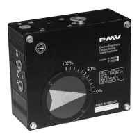
PLEASE NOTICE: For easy
acsess to important parts
please back off the four screws.
Remove the cover.
Fig 1
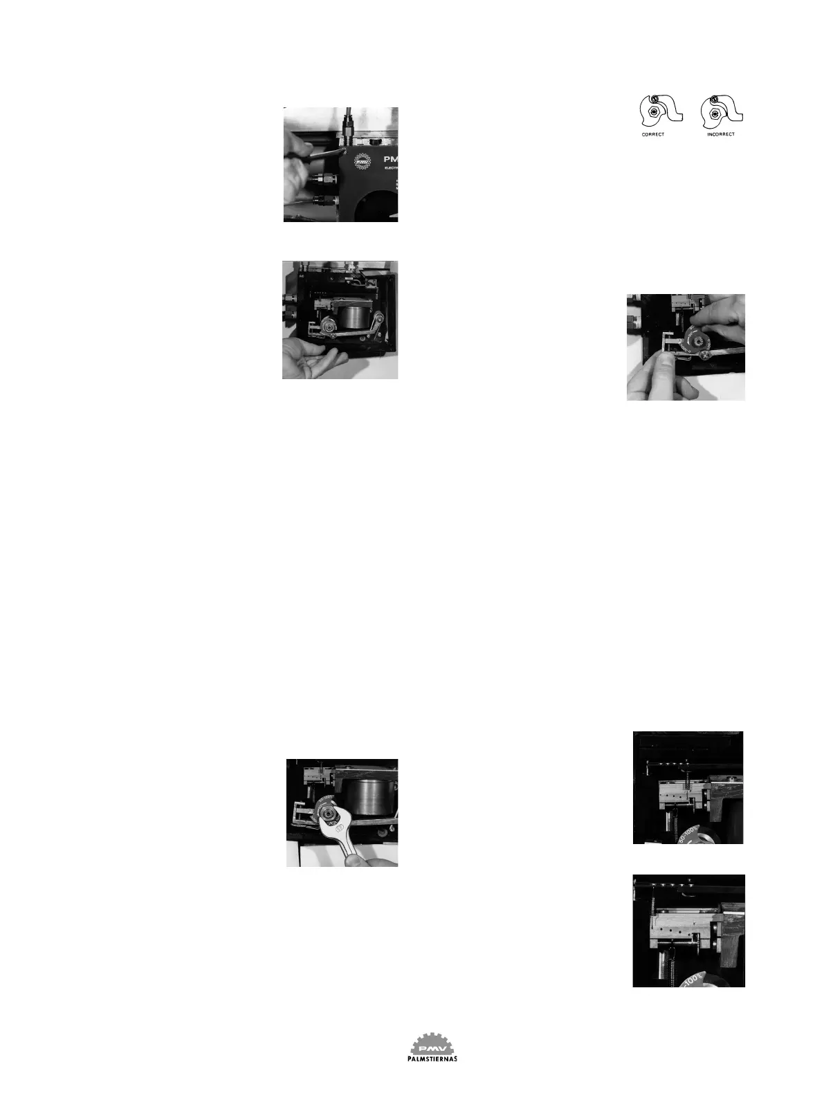
The side frame can be removed
by simply pressing out one end
of the frame from the slot in
the main frame.
Fig 2
NOTE: P-2000 series positio-
ner are factory calibrated to
4-20 mA input signal. Start
by adjusting zero rst, then
stroke the unit and check
reading before further ad-
justments.
1.1 Cam setting
After mounting the PMV
Positioner on your actuator
and before switching on the
supply air, if possible, ma-
nually operate the actuator
from fully open to fully clo-
sed position and check that
the cam is correctly oriented.
Make adjustments if necces-
sary (see instructions below).
Should manual operation of
the actuator not be possible we
recommend you to back off the
nut holding the cam.
Fig 3
Adjust the position of the cam
so that the ball bearing on the
lower arm rests on the lowest
part on the correct curve of
the cam. You have three dif-
ferent curves to choose from
on the standard cam (0-100,
0-50 or 50-100 % of the control
signal for the full stroke of the
actuator).
Position the cam as shown. The
ball bearing should not ride
on the inactive portion of the
cam. Tighten the nut.
Fig 4
NOTE: The cam will turn
slightly with the nut as it is
tightened. Be sure to allow for
this slight clockwise rotation.
1.2 To change the action
To change the action, the cam
must be ipped over and the
tubes to the connections C1
and C2 must change places.
Fig 5
1.3 Gain adjustment
PLEASE NOTE: Before adjus-
ting the gain please switch of
the supply pressure.
The gain surpression spring
can be moved along the beam
and the balance arm. The
feedback stiffness can thus
be adjusted so that the PMV
Positioner dynanics matches
the actuator size.
Fig 6&7
You will nd a number of posi-
tioning holes in the beam and
the balance arm for the spring.
The smaller the actuator the
lower is the acceptable level
of the gain.
High gain
Low gain