Manual
– 8 –
Figure 8
Figure 9
Figure 11
Figure 12
Figure 13
Figure 14
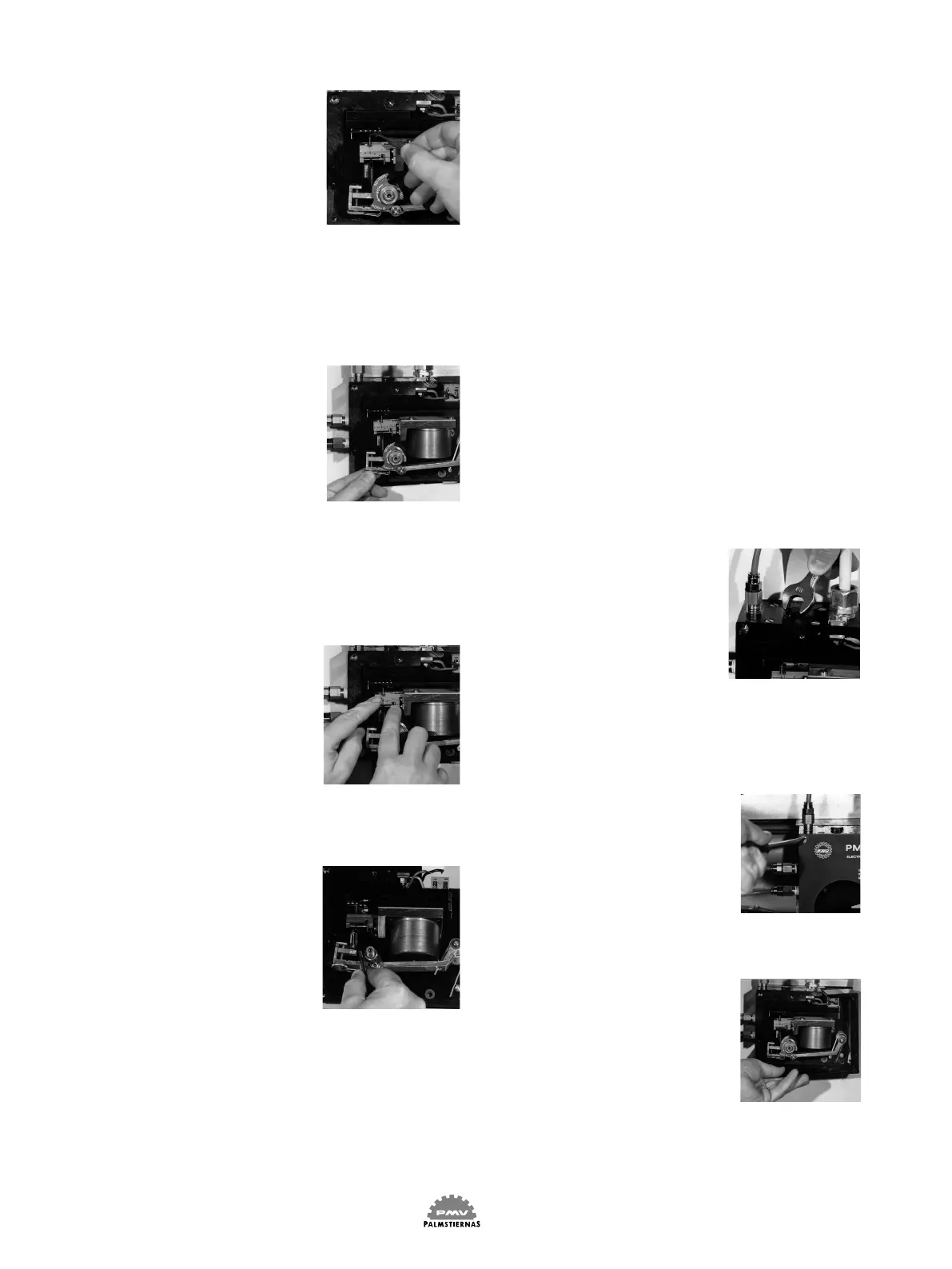
1.3.1 To reduce the gain
Move the spring to the left.
Please use a pair of tweezers
when moving the spring.
Fig 8
Changing the position of the
spring effects the zero adjust-
ment and new zero adjustment
is neccessary (see 1.4 below).
1.4 Zero adjustment
Set the input signal at 4 mA
(or 0 mA for 0-20 mA control
range) and switch on the air
supply.
When turning the zero setting
screw to the right the actuator
will move in the direction of
the decreasing signal. Adjust
the screw until the actuator is
in the ”starting” position.
Fig 9
1.5 Range adjustment
Set the input signal at its nal
value e.g. 20 mA.
If the turning angle of the
actuator is too large (small) a
downwards (upwards) rota-
tion of the range adjustment
screw will reduce (increase)
the actuator travel.
Fig 10
The range and zero adjust-
ments has a small effect on
one and other. Therefore a
few zero and range adjust-
ments might be needed in
turns.
PLEASE NOTICE: Should tbe
zero adjustment reach the limit
you might be helped by using
the other spring mounting on
the spring guide. Use a pair of
tweezers to change the posi-
tion of the spring.
Fig 11
2. Maintenance
The permanent magnet has
a very strong magnetic eld
and in order to avoid iron dust
entering into the narrow gap
for the force coil you should
never leave the PMV E/P
Positioner without the cover
mounted.
Regular maintenance of the
PMV E/P Positioner is not
required. The need for main-
tenance is depending on your
supply air quality. Should iron
dust enter into the magnet,
restricting the free movement
of the force coil , this would
cause distur-bances.
2.1 The restriction plug
Close to the connection (S)
for the supply air you will
find the restriction plug
which is easily removable
for exchange. Before repla-
cing the restrictor plug please
check that the Orings are in
good condition.
Fig 12
2.2 To clean the vahe body
Unscrew the four screws and
and remove the cover.
Fig 13
Remove the side frame.
Fig 14
Figure 10