– 9 –
Manual
Figure 16
Figure 17
Figure 18
Figure 19
Figure 20
Figure 21
Figure 22
Figure 15
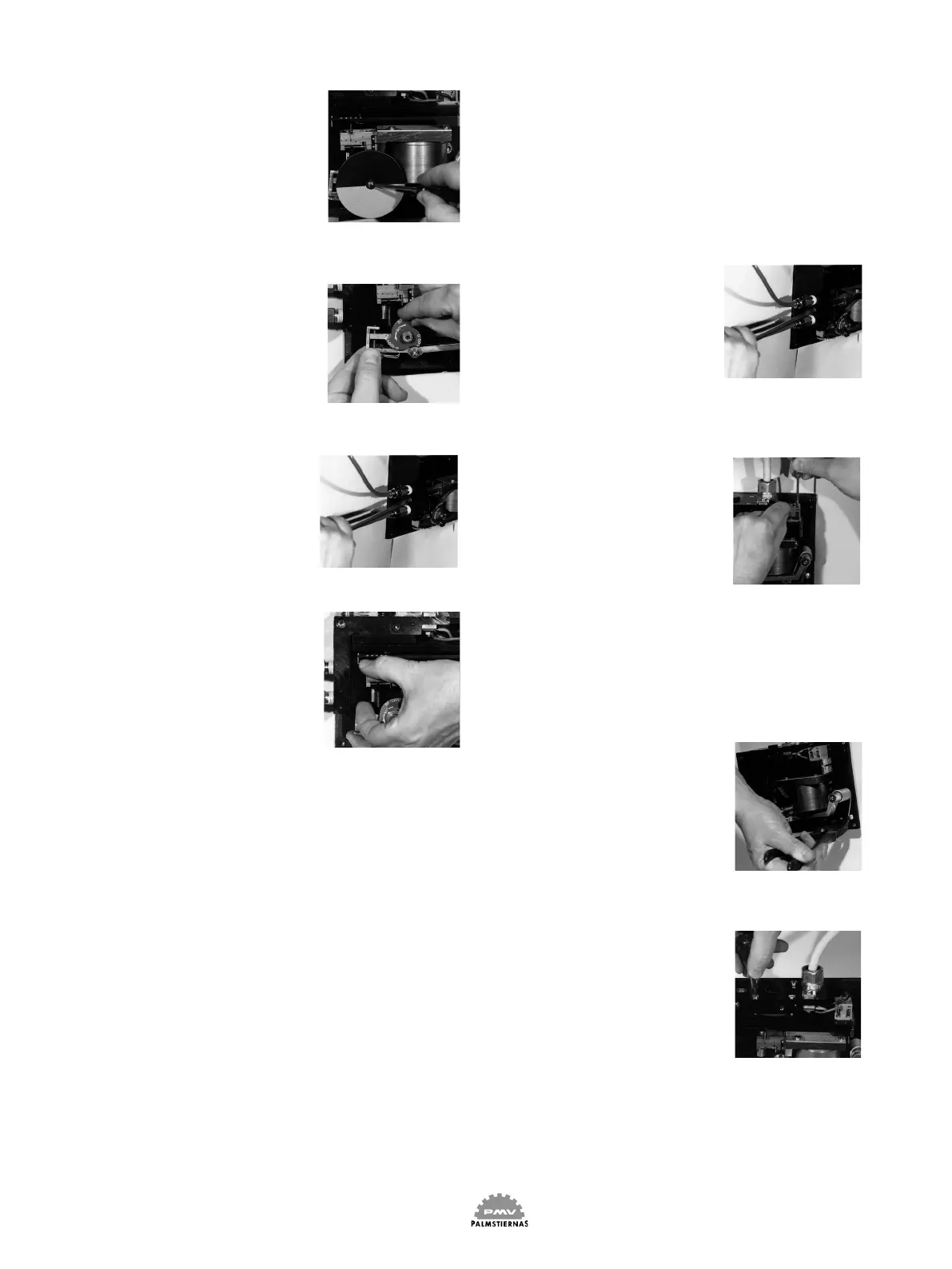
Remove the screw (30) and the
indicator.
Fig 15
Remove the nut and the cam.
Fig 16
Remove the three screws hol-
ding the valve body.
Be careful not to damage the
Magnet unit.
Fig 17
Carefully remove the valve
body. Handle so that the spool
slides easily and does not bind
against the tip of the balance
arm.
Fig 18
Pull the spool out of the valve body.
Wash the components in a solvent using e.g. a pipe-
cleaner for the valve body and blow the internal of the
valve body clean and dry using compressed air.
Parts should be handled with caution. Spool and valve
body are matched together and can not be changed
separately.
The spool should move freely in the valve body and
with the spool oriented in the ”closed position” the
play between the spool and the valve body seats
should be fairly tight. Should it be possible to move
the spool in the radius direction due to wear or if the
spool cannot be moved freely along its axes the valve
body with the spool must be exchanged.
Before retting the valve body and spool check that
the O-rings are mounted and in good condition. Take
care not to damage the leaf springs on the tip of the
balance arm. Both leaf springs must be in the gap of
the spool. Using a small screw driver to atten the leaf
springs will help you slide the spool in place.
Fit the screws and tighthen the screws a little at a
time.
Fig 19
2.3 To replace the diaphragms
Back off the four screws and
remove the cover. See g 13.
Remove the sideframe. See
fig 14. Remove the screw
and the indicator . See g 15.
Remove the nut and the cam.
See g 16.
Disconnect the control signal
wires.
Fig 20
Use a pair of plairs to unload
the tension of the spring by
lifting the end of the spring
over the screw.
Fig 21
Remove the screws and
the valve body. See g 17
and 18.
Remove the screws.
Fig 22