Installation Procedure
Once the desired cable routing is complete the wall can
be drilled using the template provided, avoid using the
POD-Point at a drilling template as resulting accidents
or debris may result in damage to the unit.
The Pod-Point can now be tted to the wall using
appropriate xings, once in place, the rear unit should
be securely xed at to the wall, avoiding warpage of
the rear housing.
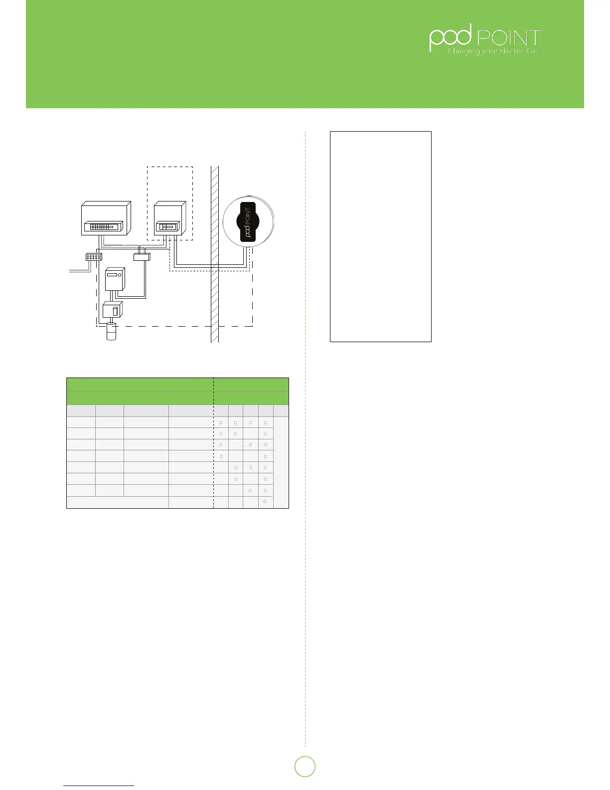
Earth Arrangements (See Fig. 5)
The Pod Point Solo features an on-board monitoring
system to detect low voltage supplies and potential
earth problems, If such a condition is encountered the
charge
cycle is ended and the
vehicle becomes isolated
from the incoming supply
and eectively becomes
double insulated. These
features emit the need
for the installation of
an earth electrode and
the POD Point Solo unit
can safely be connected
directly to a TN-C-S (PME)
earth system without any
special arrangements.
The POD Point Solo
complies with regulation
544.14.1 of BS7671.
The earth input of the
Pod-Point may also be
connected to a TT earth,
If an adjacent installation
(within 10 meters)
has a PME earthing arrangement where the POD
Point Solo would be connected to a TT system it is
imperative that the risk assessment is conducted. If a
TT earth system must be tted to the POD Point Solo,
it shall be independent from the distributors earth
system with no direct interconnection (the incoming
supply SWA protective earth should be isolated from
the housing and/or earth electrode). The electrical
installer shall install a suitable electrode complete with
termination housing and covers where appropriate,
warning labels should be visible and close to the
unconnected SWA protective earth (e.g inside the Pod-
Point).
The earth connection shall be made from the electrode
to the POD Point Solo via copper conductor earth wire
of an appropriate CSA for the installation. The earth
wire shall be installed in conduit where there is a risk of
mechanical damage or UV exposure.
Where installations are located inside of a building the
PME earth maybe used for both tethered and socketed
home chargers.
Where the charge cable may enable charging
outside of the garage area it is advisable that a risk
assessment is undertaken to ensure conductive xtures
in the equipotential zone do not pose risk.
In some installations, additional bonding maybe
required for external metallic structures, metal garages,
iron fences etc. if the vehicle or EVSE could come into
contact with the structure (i.e. if the structure and
vehicle can be touched simultaneously).
* Additional Note: TT Electrode impedance
recommended to be < 100 ohms.
** POD Point Solo used on lolipod stands must use SWA
cable. T+E cable is not allowed unless earth can be
proved to be safe.
Note for RCD
The IET code of practice
stipulates that all RCD’s
meet BS EN61008, BS
EN61009 and BS EN60947-
1or equivalent that
disconnect both live and
neutral conductors and
“specify” a Type A RCD/
RCBO to be tted. Type B
may also be used.
The minimum requirement
for the POD Point Solo
is a 30mA Type A RCD is
installed in the consumer
unit - (iΔn) not exceeding
0.03A and an operating
time not exceeding 40ms
at a residual current of
5 iΔn, with an additional
MCB.
Table A.
Circuit protection and Power rating settings
Existing Consumer Unit
Bonding
MID
Meter
Henley
Fuse
also be tted additionally
New Consumer
Unit Type A
RCD / C Curve
MCB or RCBO
OutsideInside
For TN-S Option
For TN-C an electrode can
TT Earth Option
Fig 5.
Typical Schematic of installation circuit
*The Pod Point also provides internal over-current protection in addition
to the above
Cable CSA
Power Rating
1Phase
3.1kW
2.4kW
1.4kW
MCB * / RCBO
Switch Setting
13Phase 432
6kW
4.8kW
3.7kW
POD Disabled
7.2kW
9.4kW
7.2kW
4.3kW
18kW
14.4kW
11kW
21.6kW
16A
16A
10A
32A
32A
20A
40A
1.5mm
2


 To Next Page
 Loading...