Do you have a question about the PoKeys 56U and is the answer not in the manual?
Product integration and user responsibility for safety and compliance with regulations.
Upgrade of original pulse engine for step/direction systems.
Limits axis movement within a specified range, allowing free movement in the other direction.
Assigns different encoders and supports MPG for operation.
Dedicated input to stop pulse generation when activated.
Supports up to 3 axes at 25 kHz step frequency.
Supports up to 8 axes at 125 kHz using external adapter.
Supports up to 8 axes at 125 kHz with dedicated IO capabilities.
Details pin assignments for step/direction outputs and emergency switch input.
Describes connecting the PoKeysCNCaddon to the PoKeys device via Expansion port.
Configuration for limit, home, and reference switches using dedicated pins.
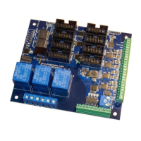
Features 3 normally-open relay outputs with specified ratings.
Generates a 0-10V analog output using PWM signal and a low-pass filter.
Includes inputs for spindle error and general-purpose external signals.
Specifies maximum/minimum position limits for internal and external modes.
Steps to copy the DLL and install the PoKeys software.
Lists features like multi-axis support, input/output mapping, and MPG support.
Guide to opening Mach3 and configuring the plugin for the first time.
Uses the integrated pulse engine for step frequencies up to 25 kHz.
Uses external adapter for step frequencies up to 125 kHz.
Uses PoKeysCNCaddon for step frequencies up to 125 kHz.
Configuring steps per, velocity, and acceleration for each axis.
Setting up software limits, homing speeds, and axis directions.
Configuring limit, home, and probing switches with dedicated/standard pin options.
Shared limit functions and temporary disabling of limit functionality.
Mapping PoKeys digital inputs/outputs to Mach3 OEM LEDs.
Mapping PoKeys digital inputs to Mach3 OEM buttons.
Mapping PoKeys IOs to Mach3 internal IOs for control and status.
Enabling pendant mode for MPG jogging with activation switch.
Table and diagram for connecting PoPendant and mapping pins to Mach3.
Enabling encoders, setting resolution, and mapping to DROs.
Configuring encoders as MPGs for jogging, mapping to DROs.
Configuring matrix keyboard dimensions and pin assignments.
Enabling LCD, selecting pins, size, and editing contents.
Setting up user labels, variables, and formats for each LCD row.
Configuring PWM outputs, mapping to DROs, or assigning fixed values.
Mapping analog inputs to joystick axes for jogging control.
Calibrating analog inputs for accurate joystick functionality.
Options for connection failure reset, unavailable device display, and shared data interchange.
Using VB script functions to read/write PoKeys IO pins.
List of OEM LED functions for jogging and selection increments.
Overview of pulse engine states, switch configuration, and motion parameters.
Describes modes like Stopped, Error, Homing, and Probing.
Explains MPG jogging and Running modes, including buffer and internal control.
Controls motor driver enabling, often linked to safety charge-pump settings.
Defines parameters for motion like max speed, acceleration, and switch configurations.
Details a circuit for deserializing step/direction data using 74HCT595 IC.
Addresses blinking reset and motor power engagement with stepper drivers.
Configuring spindle control using PWM output and DRO mapping.
| Input Voltage | 5V DC |
|---|---|
| Number of Inputs | 56 |
| Communication Interface | USB |
| Input type | Digital, Analog |
| Number of analog inputs | 8 |
| Number of PWM outputs | 8 |
| Power supply | USB |
| Storage temperature | -20-85°C |
| Humidity | 5% to 95% (non-condensing) |