EasyManua.ls Logo

POLA HP54 - User Manual

POLA HP54
2 pages
Print Icon
To Next Page IconTo Next Page
Loading...
HEAT TEMPERATURE SETTING.
Press HEAT:
This message will be displayed instead of the
°Set Heat temperature value .
Press + or - to modify, press HEAT to exit.
VENTILATION TEMPERATURE SETTING.
Press VENT:
This message will be displayed instead of the
°Set Ventilation temperature value (start first step).
Press + or - to modify, press VENT to confirm.
At this point: this message will be displayed instead of the
Minimum Ventilation Step (*).
Press + or - to modify, press VENT to confirm.
At this point: this message will be displayed instead of the
Maximum Ventilation Step.
Press + or - to modify, press VENT to confirm.
At this point: this message will be displayed instead of the
Shutter Dwell Time (seconds.).
Press + or - to modify, press VENT to confirm.
(*) If the minimum speed is set to 0, this message appears
instead of the Set Shutter Running Time (seconds).
Press + or - to modify, press VENT to confirm.
At this point: this message will be displayed instead of the
Shut Speed Number.
Press + or - to modify, press VENT to exit.
ALARM PARAMETER SETTING.
Press ALARM:
This message will be displayed instead of the
°Set Minimum Alarm temperature value .
Press + or - to modify, press ALARM to confirm.
At this point: this message will be displayed instead of the
°Set Maximum Alarm temperature value .
Press + or - to modify, press ALARM to exit.
MAIN SETTINGS (Run Mode)
How to connect the sensors
Connect the provided sensor as shown in the
diagram. For remote connections use a
standard 0.5-square millimeter two-pole wire
, taking great care over the connections, by
insulating and sealing the joins carefully. -O.C.-
is displayed when the temperature sensor wiring
is open, -S.C.- is displayed when the
temperature sensor wiring is short circuit.
INSTALLATION
How to connect the contacts
Output contacts are N.O. (Normally
Opened free of voltage) on wich is apliable
a 4AMP AC1 maximum load.
3-4= Step 1 contact
3-5= Step 2 contact
3-6= Step 3 contact
3-7= Step 4 contact
11-12= Heat contact
12-13= Cool contact
Alarm and Cooling are available only with
HPAL optional slot.
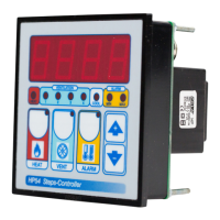
STATUS INDICATION LAMPS
HP54
Handbook
SL 3.1
4 step ventilation + thermoreg.
Lamp. Relay
HEAT 0 1 2 3 4
HEAT 1
0 0 0 0 0
5
VENT 1
0 0
1
0 0 0
1
VENT 2
0 0
1 1
0 0
2
VENT 3
0 0
1 1 1
0
3
VENT 4
0 0
1 1 1 1 4
Lamp. Relay
HEAT 0 1 2 3 4
HEAT 1
0 0 0 0 0
5
VENT 1
0 0
1
0 0 0
1
VENT 2
0 0 0
1
0 0
2
VENT 3
0 0 0 0
1
0
3
VENT 4
0 0 0 0 0
1 4
Output relay
Table of relay Outputs with tYPE= 1-2-3-4-13 (Variable speed control)
Output relays with tYPE = 14 (see COSt)
Table of relay Outputs with tYPE = 14 (On-Off regulation type)
The lights situated at the bottom of the display show the state of the relay.
How to connect the line
Connect 230V line on terminals L-N.
Protect supply with adequate fuse.
COOL
COMMON
HEAT
HP54
* Other power voltage if you required
230V LINE *
COMMON
STEP 4
STEP 3
STEP 2
STEP 1
SX TEMPER.
PROBE
As it company policy to continually improve the products the Manufacturers
reserve the right to make any modifications thereto without prior notice. They
cannot be held liable for any damage due to malfunction.
12.02.13
Question and Answer IconNeed help?

Do you have a question about the POLA HP54 and is the answer not in the manual?

Summary

Status Indication Lamps Overview

Relay Outputs for Variable Speed Control

Details relay output states for variable speed control types (1-2-3-4-13).

Relay Outputs for On-Off Regulation

Details relay output states for On-Off regulation types (14).

Installation and Wiring Guide

Connecting the Power Line

Instructions for connecting the 230V power line and necessary fuse protection.

Connecting Temperature Sensors

Guidance on connecting sensors and troubleshooting open/short circuit wiring.

Wiring Output Contacts

Information on connecting Normally Opened (N.O.) contacts and their load capacity.

Main Settings and Operation Modes

Heat Temperature Setting

Procedure to display and modify the desired heating temperature.

Ventilation Temperature and Step Settings

Setting ventilation temp, min/max steps, and shutter running times.

Alarm Parameter Configuration

How to set minimum and maximum temperature values for alarms.

Temperature Monitoring and Manual Mode

Viewing Temperature Records

How to view recorded maximum and minimum temperature values.

Manual Mode Operation

Instructions for entering Manual Mode and activating relays.

System Constants and Programming

Initial System Constant Setup

Guidance on setting system operation modes during initial startup.

Heat and Ventilation Differential Settings

Configuration of heat and ventilation differential parameters.

Ventilation Step and Mode Configuration

Setting ventilation steps and start-up actioning modes.

Cost Function Type for Speed Control

Understanding how COST function type influences speed transitions.

Operative Diagrams and Presets

Cyclical Minimum Speed Operation Diagram

Diagram explaining cyclical minimum speed with zero minimum speed setting.

Heater Mode Ventilation Diagram

Visual representation of ventilation operation in heater mode.

Restoring Preset Program Settings

Procedure to return the device to its default preset settings.

POLA HP54 Specifications

General IconGeneral
BrandPOLA
ModelHP54
CategoryTemperature Controller
LanguageEnglish