Do you have a question about the Polar Instruments TONEOHM 850A and is the answer not in the manual?
Product hardware warranted free from defects in material & workmanship during the Warranty Period.
Polar not liable if end user fails to provide timely notice of alleged defects.
End user must notify Polar & carrier of transit damage within 2 days of receipt.
Polar's liability & end user's remedy limited to express remedies in this warranty.
POLAR MAKES NO OTHER WARRANTIES, EXPRESS, IMPLIED OR STATUTORY, REGARDING PRODUCTS.
POLAR NOT RESPONSIBLE FOR DIRECT DAMAGES EXCEEDING PURCHASE PRICE PAID BY END USER.
Product conforms to applicable EC Council Directives on electromagnetic compatibility and voltage limits.
Unit contains no user-serviceable parts. Opening covers may expose dangerous voltages.
Instrument must be earthed and connected to an outlet with an effective protective conductor terminal.
Details standard color coding for power cords in Europe and the United States.
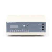
An overview of the Polar TONEOHM 850A shorts locator and its applications.
Explains three operating modes: Milliohmmeter, Track Voltage, and Current Trace for fault finding.
Details various applications requiring low resistance measurements.
Describes the digital display and audio tone output features.
Details three modes: Milliohmmeter, Track Voltage, and Current Tracer for fault finding.
Describes the front panel controls, connectors, and probes for operation.
Details the ON/OFF switch and IEC mains inlet connector on the rear panel.
Provides guidelines for selecting appropriate modes and ranges based on fault type.
Covers unpacking the instrument and its accessories.
Instructions for connecting the instrument to a suitable mains power supply.
Techniques for identifying low resistance shorts using the milliohmmeter range.
Applies milliohmmeter techniques to double-sided boards, noting challenges on dense boards.
Illustrates finding a short circuit using the milliohmmeter by tracking readings and tone.
Explains tracing current via voltage drops for loading faults and high resistance shorts.
Describes using the Drive Source for static faults and specific ranges for PCB tracks.
Details identifying faults where a Vcc rail is held low by excessive current draw.
Covers testing powered-up boards to trace current flow and identify faults causing excess current.
Useful for tracks/components difficult to access, like dense PCBs, cable looms, or inner layers.
Explains using the Drive Source to inject current & probe to detect magnetic field.
Guides on connecting leads, adjusting Drive Source control, and optimizing probe sensitivity.
Describes tracing current paths, board sectoring, and finding faults within a small area.
Locating faults on bus lines where parallel capacitors are absent.
Detecting shorts between pins of edge connectors using Drive Source and probe.
Using TRACE to identify open circuit decoupling capacitors by sensing current flow.
Instructions for cleaning the instrument using water, mild detergent, or alcohol.
Information on contacting Polar Instruments or distributors for technical assistance.
| Power Supply | 100-240 VAC, 50/60 Hz |
|---|---|
| Accuracy | 0.02% |
| Interfaces | RS-232, USB |
| Test Current | Up to 1A |
| Display | LCD |