EasyManua.ls Logo

Polaroid TLM-23201B User Manual

Polaroid TLM-23201B
70 pages
To Next Page IconTo Next Page
Page #1 background imageLoading...
Page #1 background image
32LCD TV Polaroid TLM-23201B
1
Service
Service
Service
Horizontal Frequency
31~60 kHz
TABLE OF CONTENTS
Description Page Description Page
SAFETY NOTICE
ANY PERSON ATTEMPTING TO SERVICE THIS CHASSIS MUST FAMILIARIZE HIMSELF WITH THE CHASSIS
AND BE AWARE OF THE NECESSARY SAFETY PRECAUTIONS TO BE USED WHEN SERVICING
ELECTRONIC EQUIPMENT CONTAINING HIGH VOLTAGES.
CAUTION: USE A SEPARATE ISOLATION TRANSFOMER FOR THIS UNIT WHEN SERVICING
6.1.Main Board…………..……………...……….......25
6.2.Power Board……………..………….……….......28
6.3.Key Board………………………..……….......29
6.4 IR Board………………………..……….......29
7. Adjustment………………………………............30
8. Block Diagram.……...........................................31
9. Schematic……………...…………..………………...32
9.1 Main Board…………………………………...….......32
9.2.Power Board…………….…………...………….......46
9.3.Key Board……………….……….………….......47
10. Exploded View………………………………….…...48
11. BOM List……………….…………………………….50
Table Of Contents.......……..............................…........1
Important Safety Notice.......................................……......2
Revision List…………………………………………………3
1. General Specification..............................………........4
2. Operating Instructions…………………….……….......6
2.1. The Use Of Remote Control…….………….…….......6
2.2. To Use The Menu…...…………………….……….......7
2.3. How To Connect…….…………………….……….....13
2.4. Front Panel Control Knobs……………….……….....14
3. Input/Output Specification…………....................…....15
4. Mechanical Instructions…………………….................17
5. Repair Flow Chart ……………………….…….…….....20
6. PCB Layout ………………..………………....….......25
Question and Answer IconNeed help?

Do you have a question about the Polaroid TLM-23201B and is the answer not in the manual?
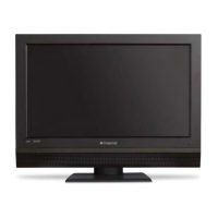
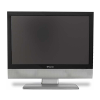
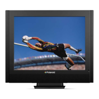
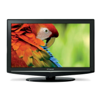
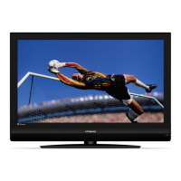
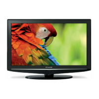
Polaroid TLM-23201B Specifications

General IconGeneral
Display TechnologyLCD
Screen Size23 inches
Resolution1366 x 768
Aspect Ratio16:9
Refresh Rate60 Hz
InputsHDMI, Composite, VGA
Sound Output10W (2 x 5W)

Summary

Important Safety Notice

General Safety Precautions

Covers warnings, laser safety, replacement parts, and handling of the LCD module.

Revision List

General Specification

Operating Instructions

Remote Control Usage

Explains the function of each button on the TV remote control.

Menu Navigation and Settings

Guides users on navigating and adjusting TV settings via the OSD menus.

Video Menu Adjustments

Details adjustments for contrast, brightness, sharpness, color, tint, and backlight.

Audio Menu Adjustments

Covers audio adjustments like bass, treble, balance, and digital audio output.

Feature Menu Options

Explains settings for time, sleep timer, advanced video, password, and parental controls.

Password and Parental Control Settings

Guides on changing the parental password and setting up parental locks.

Digital Caption and Display Settings

Covers closed captions, component, and VGA display settings.

How to Connect

Front Panel Control Knobs

Input/Output Specification

RGB and HDMI Input Details

Details pin assignments and specifications for RGB and HDMI inputs.

AV, S-Video, Component Inputs & Modes

Explains AV/S-Video/Component inputs and compatible video modes.

Mechanical Instructions

Repair Flow Chart

Troubleshooting: No Power

Step-by-step guide for diagnosing and fixing no-power issues.

Troubleshooting: Cannot Start

Diagnostic steps for when the TV fails to start with LED indicator yellow.

Troubleshooting: No Display

Procedure for resolving issues where the screen shows no image but LED is green.

Troubleshooting: Abnormal Display

Steps for fixing distorted or incorrect video output.

Troubleshooting: No Sound

Guide to diagnose and fix audio output problems.

Troubleshooting: Key Board Issues

Steps for diagnosing problems related to the TV's physical buttons.

PCB Layout

Main Board Layout

Visual representation of the main printed circuit board components.

Power Board Layout

Visual representation of the power supply board components.

Key Board and IR Board Layout

Visual representation of the key and IR remote sensor board components.

Adjustment

Block Diagram

Schematic Diagram

Main Board Schematic

Detailed circuit diagram for the main printed circuit board.

Power Board Schematic

Detailed circuit diagram for the power supply board.

Key Board Schematic

Circuit diagram for the key input board.

Exploded View

BOM List

Related product manuals