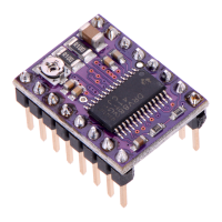
CONTROL INPUTS
Each pulse to the STEP input corresponds to one microstep of the stepper motor in the
direction selected by the DIR pin. These inputs are both pulled low by default through
internal 100kΩ pull-down resistors. If you just want rotation in a single direction, you
can leave DIR disconnected.
The chip has three different inputs for controlling its power states: RESET, SLEEP,
and ENBL. For details about these power states, see the datasheet. Please note that the
driver pulls the SLEEP pin low through an internal 1MΩ pull-down resistor, and it pulls
the RESET and ENBL pins low through internal 100kΩ pull-down resistors. These
default RESET and SLEEP states are ones that prevent the driver from operating; both
of these pins must be high to enable the driver (they can be connected directly to a
logic “high” voltage between 2.2 and 5.25 V, or they can be dynamically controlled via
connections to digital outputs of an MCU). The default state of the ENBL pin is to enable
the driver, so this pin can be left disconnected.

 Loading...