Do you have a question about the Polon-Alfa DOP-6001R and is the answer not in the manual?
Outlines safety requirements and responsibilities for servicing and repairing the detector by authorized personnel.
Details safety precautions for detector installation work performed at height using appropriate tools and machinery.
Mandates the use of eye protection during dust-generating installation procedures like drilling.
Requires specific eye protection against direct laser exposure when using the laser viewfinder for alignment.
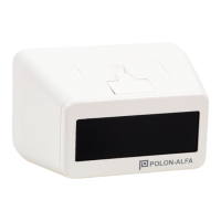
The DOP-6001R Optical Beam Smoke Detector is designed for early smoke detection in various premises, particularly those with large open spaces or high ceilings where traditional spot smoke detectors might be less effective. Its primary function is to continuously monitor the optical transparency of the air between the detector and a reflector, triggering an alarm when a defined quantity of aerosol (smoke) reduces this transparency below a set threshold.
The detector operates on the principle of an infrared (IR) light transmitter and a receiver housed within a single enclosure. This unit interacts with a separate E39-8R prism reflector or a 4xE39-8R reflector panel positioned on an opposite wall or structure. The IR beam is emitted by the transmitter, reflects off the prism or panel, and returns to the receiver. By continuously analyzing the intensity of the returned beam, the detector assesses the air's transparency.
The DOP-6001R can operate in three distinct modes:
A key feature of the DOP-6001R is its automatic compensation for contamination and environmental impacts. Over time, especially in dusty environments, optical parts of both the detector and the reflector/reflector panel can accumulate dirt. The detector's internal circuits monitor this contamination and adjust its sensitivity to maintain consistent fire detection capabilities. When contamination reaches a certain level, the detector signals a fault, indicating the need for cleaning, but it continues to function as a smoke detector. After cleaning, the detector can be re-adjusted to new external conditions and return to supervision mode.
The detector's analysis function is managed by a microprocessor. After initial optical path adjustment and pressing the START button, the microprocessor analyzes ambient temperature and the selected sensitivity threshold. A self-adjustment program then runs to establish a reference value within a ±5% tolerance. This data is stored in the detector's non-volatile memory and periodically checked. Any significant change in the measured value (against assumed decision thresholds) caused by smoke, after triple verification, is interpreted as a fire.
The DOP-6001R is designed to interoperate with any fire detection and alarm control panel that provides power within the range of 9.5 V to 28 V and a current greater than 100 mA. Its alarm signal is provided via non-potential relay contacts.
The DOP-6001R is particularly suited for premises where a large number of spot smoke detectors would otherwise be required due to extensive space. Its ability to detect smoke over a long infrared radiation beam path makes it ideal for high ceilings/roofs or areas where smoke might diffuse over a large area before detection. Examples include churches, cathedrals, monumental buildings with valuable historic ceilings, theaters, sports halls, industrial shops, very high rooms, and rooms with differentiated ceiling or roof designs.
A distinctive feature is the integration of both transmitter and receiver in a single enclosure, simplifying installation. It also includes a laser target viewfinder to facilitate precise optical path axis alignment between the detector and the reflector/reflector panel.
Installation involves mounting the detector on one wall or pillar and the reflector/reflector panel on an opposite, stable, and vibration-free surface. The detector's adjustment base is used for mounting. Before installation, the desired alarm mode and sensitivity threshold must be set using jumpers on the back of the detector casing. Recommended sensitivity levels vary based on the operating distance: 18% for 5-20m, 30% for 20-50m, and 50% for 50-100m. Experimental setting of sensitivity is also possible for challenging operating conditions.
Alignment of the detector's optical path is a critical step. A mirror from the service kit is temporarily placed on the reflector panel, and the detector's laser beam is aimed at its center using three positioning screws. This ensures the laser beam reflects back to the detector's front plate. Once aligned, the mirror is removed. The prism reflector, being non-adjustable, should be fixed to a flat substrate. The alignment process, which takes approximately 30 seconds, is initiated by pressing the START button. During this process, the detector signals a fault to the control panel. Correct alignment is indicated by a green LED flashing every 10 seconds. If a yellow LED flashes after adjustment, it indicates a failed adjustment. It is recommended to perform alignment in a dark room and avoid direct sunlight exposure on the detectors.
For installations where the detector is difficult to see or access, an optional WZ-31 additional operation indicator can be connected and placed in a more convenient location.
Long-term operation, especially in dusty environments, can lead to contamination of the detector's optical parts and the reflector/reflector panel. The detector's automatic compensation system will signal a fault when contamination exceeds a programmed threshold, indicating that maintenance is required. This fault notification means that cleaning of the reflector/reflector panel and the detector's front surface is necessary. After cleaning, the START push button must be pressed to re-adjust the detector to the new external conditions, after which it will automatically return to supervision mode.
Regular maintenance inspections should include checking the detector's proper operation. This can be done by partially obscuring the detector's optical path using a special damping plastic foil (included in the service kit) with overprints corresponding to the detector's three sensitivity levels (18%, 30%, 50%). Placing the appropriate foil on the detector's front plate should trigger an alarm.
During renovation or painting works in premises where detectors are installed, it is crucial to either remove or protect the detector and its reflector/reflector panel. Damage incurred during such works due to negligence is not covered by warranty repairs.
All maintenance works, periodic inspections, and repairs must be carried out by skilled personnel authorized or trained by POLON-ALFA. The manufacturer disclaims responsibility for apparatus serviced or repaired by unauthorized personnel.
Safety precautions are essential during installation and maintenance. When working at height, appropriate tools and machinery in good condition should be used, with particular attention to the stability of ladders and platforms. Electric tools must be used according to manufacturer safety rules. Anti-dusting glasses and masks are obligatory during installation works that generate significant dust, such as drilling. When aligning the detector's optical path with the laser viewfinder, special eye protection (3R laser equipment class) is required to prevent direct laser exposure.
| Type | Optical Smoke Detector |
|---|---|
| Alarm Current | ≤ 20 mA |
| Detection Principle | Optical (scattering of light) |
| Relative Humidity | ≤95% RH |
| Standby Current | ≤20 μA |