6
Setting up the Polycom HDX Ceiling Microphone Array Series
For suspended ceilings
4 (cont.)
d
c
50’ (15.2 m)
~
10’
(3.1 m)
For Polycom TPX HD 306M Systems
(cont.)
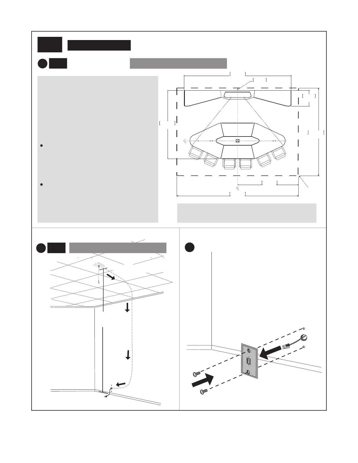
For Polycom TPX HD 306M Systems, you must
position the two Ceiling Microphone Arrays
relative to the multipurpose table. Therefore,
before installing the first Ceiling Microphone
Array, you must use the measurements at the
right to determine the placement of the creden-
za and the multipurpose table in your room.
When determining the placement of the Ceiling
Microphone Arrays, you must ensure that:
The left Ceiling Microphone Array will be 2 ft
(61 cm) to 3 ft (91 cm) to the left of the
vertical centerline of the multipurpose table,
and will be no more than 6 in (15 cm) from
the horizontal centerline of the multipurpose
table.
The right Ceiling Microphone Array will be 2
ft (61 cm) to 3 ft (91 cm) to the right of the
vertical centerline of the multipurpose table,
and will be no more than 6 inches (15 cm)
from the horizontal centerline of the multi-
purpose table.
190.2”
483.1cm
274.3cm
108.0”
10.2cm
4.0”
121.8”
309.4cm
72.4cm
28.5”
Minimum
room size
396.2cm
156.0”
216.0”
548.6cm
Each X in the illustration above shows approximately
where the Ceiling Microphone Arrays should be placed.
c
For Polycom TPX HD 306M Systems
(cont.)
C
L
C
L
X
X
 Loading...