EasyManuals Logo

Polycom HDX Ceiling Microphone Array Series User Manual

Polycom HDX Ceiling Microphone Array Series
16 pages
To Next Page IconTo Next Page
To Previous Page IconTo Previous Page
Page #8 background imageLoading...
Page #8 background image
8
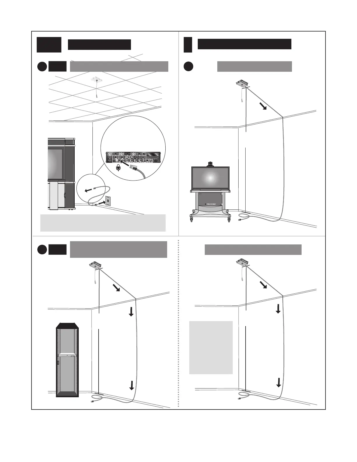
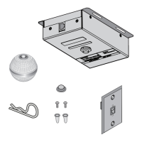
Setting up the Polycom HDX Ceiling Microphone Array Series
10’ (3.1 m)
4 (cont.)
For suspended ceilings
Primary (center)
codec in credenza
For more information, refer to the Polycom
TPX HD 306M Installation Guide.
or patch panel on side
of credenza
Refer to step
4c on page 6
for information
about Ceiling
Microphone
Array
placement.
5
For ceilings that are not suspended
50’ (15.2 m)
a
SoundStructure C16
TM
50’ (15.2 m)
For Polycom HDX Systems
~
10’
(3.1 m)
~
10’
(3.1 m)
For Polycom TPX HD 306M Systems
e
(cont.)
a
(cont.)
For Polycom SoundStructure C-Series
Systems
For Polycom TPX HD 306M Systems
50’ (15.2 m)
~
10’
(3.1 m)

Questions and Answers:

Question and Answer IconNeed help?

Do you have a question about the Polycom HDX Ceiling Microphone Array Series and is the answer not in the manual?

Polycom HDX Ceiling Microphone Array Series Specifications

General IconGeneral
BrandPolycom
ModelHDX Ceiling Microphone Array Series
CategoryMicrophone system
LanguageEnglish

Related product manuals