Do you have a question about the Polysoude MU IV Series and is the answer not in the manual?
Covers risks associated with arc welding processes and their prevention.
Explains the meaning of various safety symbols used in the manual.
Provides essential safety recommendations for operating welding equipment.
Lists relevant documents and standards associated with the equipment.
Details the European directives the equipment complies with.
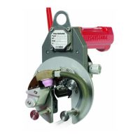
Introduces the MU IV open welding heads and their applications.
Classifies the machine based on compliance with relevant directives.
Specifies the environmental conditions required for safe and effective operation.
Provides a detailed description of the MU IV welding head components and their functions.
Outlines the welding capacities for different MU IV head models.
States the compatibility of MU IV welding heads with Polysoude generators.
Details safety precautions and methods for handling the welding head.
Covers site preparation and safety aspects for installation.
Explains how to handle and suspend the welding head using specific points.
Provides guidance on connecting and managing the equipment bundle.
Outlines essential precautions to be taken during the use of the welding equipment.
Discusses the handling, grinding, and selection of electrodes.
Explains the selection, types, and connection of wire sheaths.
Details the procedure for setting up and using the built-in wire feeder.
Provides instructions for adjusting both chuck and shell clamps.
Offers a guide to diagnose and resolve common problems with the equipment.
Details preventive maintenance tasks for ensuring equipment longevity.
Lists recommended lubricants for various components.
Describes the contents of the accessories box, including consumables.
Lists the tools required for maintenance and operations.
Provides instructions for performing repairs and specific maintenance tasks.
Explains how to clean and maintain the drive assembly.
Details the procedure for replacing the drive pin, a safety component.
Guides the user through the process of replacing the optical sensor.
Describes how to change wire feed rollers and the wheel.
Provides instructions for replacing the inner wire sheath.
Explains how to repair leaks in the multi-duct assembly.
Details the procedure for repairing a broken braid in the multi-duct.
Guides the wiring and connection of AVC/OSC components.
Explains how to wire the cooled motor for the welding head.
Details the wiring connections for the drive on the generator side.
| Brand | Polysoude |
|---|---|
| Model | MU IV Series |
| Category | Industrial Equipment |
| Language | English |