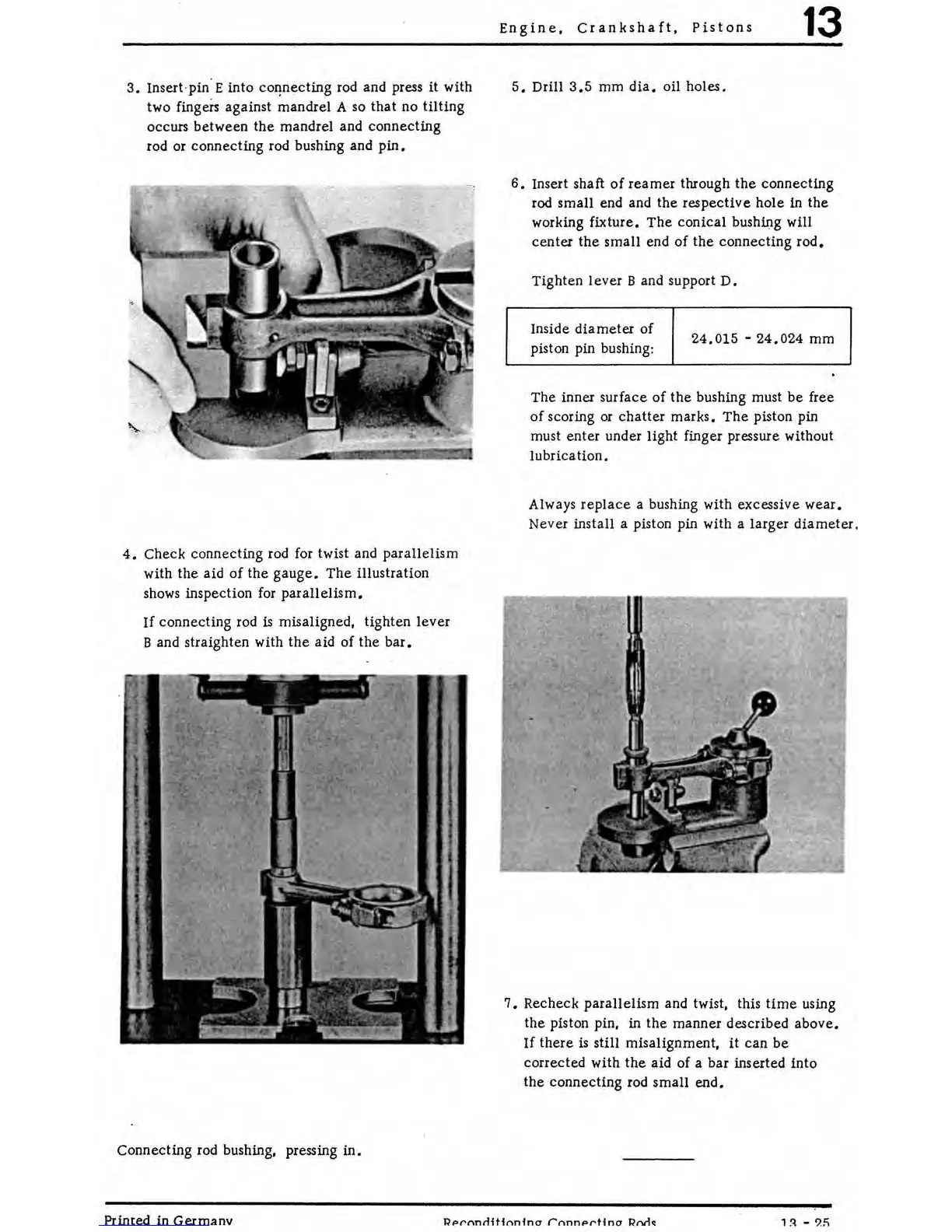
3.
Insert· pin· E into
co~necting
rod and press it with
two
fingers against mandrel A
so
that no
tilting
occurs between the mandrel and connecting
rod or connecting rod bushing and
pin.
4.
Check connecting rod for twist and parallelism
with the aid
of
the
gauge.
The
illustration
shows inspection
for
parallelism.
If
connecting rod
is
misaligned, tighten
lever
B and straighten with
the
aid of the
bar.
Connecting rod bushing, pressing
in.
Engine,
Crankshaft,
Pistons
13
5.
Drill
3.5
mm
dia.
oil holes.
6.
Insert shaft
of
reamer
through
the
connecting
rod small end and the respective hole in the
working fixture.
The
conical
bushing will
center the
small
end of
the
connecting
rod.
Tighten lever
Band
support
D.
Inside
diameter
of
piston pin bushing:
24.015
-
24.024
mm
The inner surface
of
the
bushing must be free
of
scoring
or
chatter
marks.
The
piston pin
must enter under light finger pressure without
lubrication.
Always
replace
a bushing with excessive
wear.
Never install a piston pin with a larger
diameter.
7.
Recheck parallelism and twist, this
time
using
the piston pin, in the manner described above.
If
there
is
still misalignment,
it
can
be
corrected with
the
aid of a bar inserted into
the connecting rod small
end.
Printed in Germanv
RPf'l"lnrlitfrmfncr
rnnnPf'tfncr
Rnrlo