5
Symbols
• The label on your tool may include the following symbols. The symbols and their
definitions are as follows:
V..................volts A ..................amperes
Hz................hertz W..................watts
min ..............minutes ................alternating current
............direct current
n
o ................no load speed
................Class I Construction ..................earthing terminal
(grounded) ................safety alert symbol
................Class II Construction .../minorrpm ....revolutions or reciprocation
(double insulated) per minute
• When using an extension
cord, be sure to use one
heavy enough to carry the
current your product will
draw. An undersized cord
will cause a drop in line
voltage resulting in loss of
power and overheating. The
table shows the correct size
to use depending on cord
length and nameplate
ampere rating. If in doubt,
use the next heavier gage. The smaller the gauge number, the heavier the cord.
SAVE THESE INSTRUCTIONS
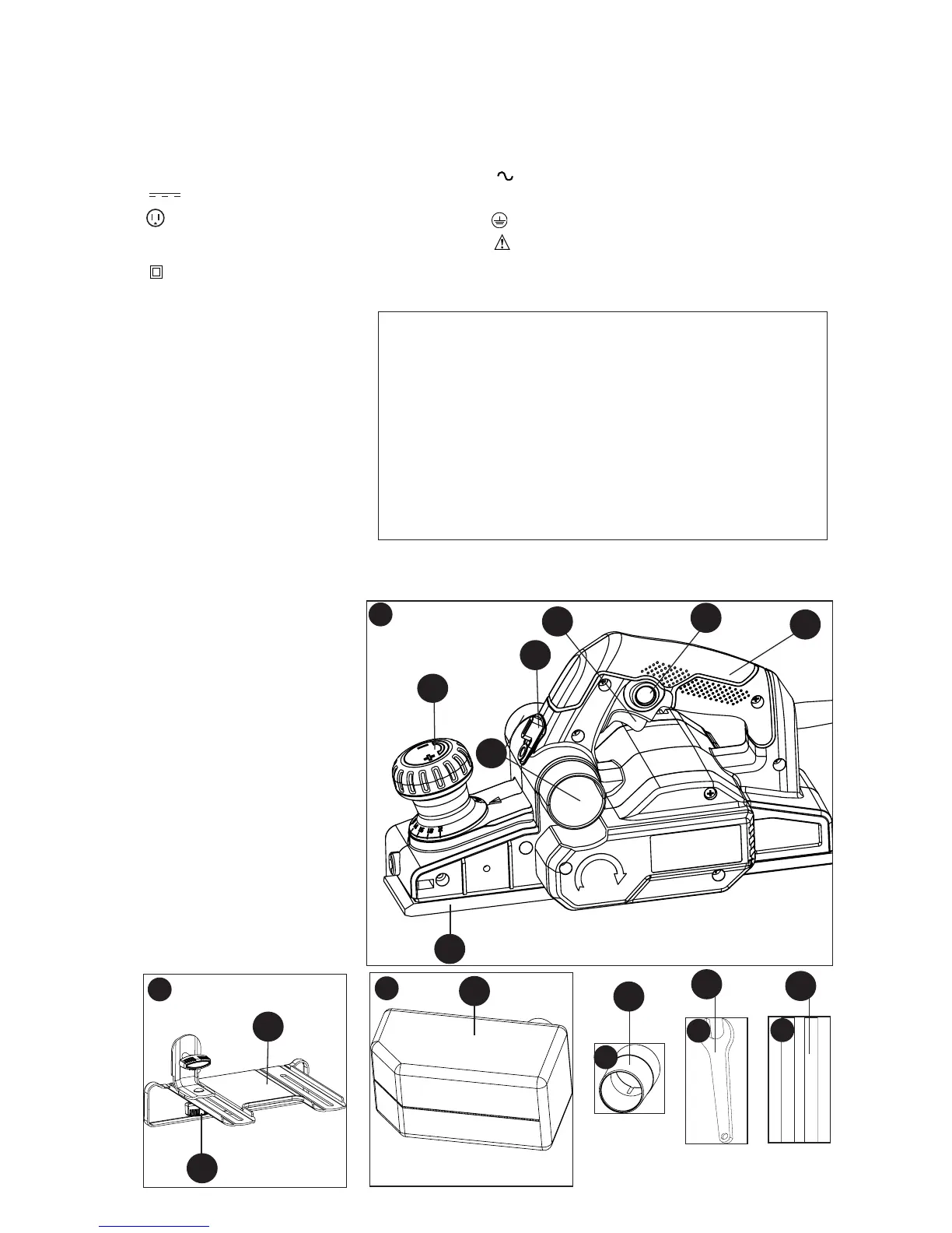
Components
A. Trigger switch
B. Lock-on button
C. Depth adjustment knob /
front handle
D. Switch Handle
E. Shoe
F. Chip discharge chute
G. Chip deflector lever
H. Rabbet fence adjustment
knob
I. Rabbet fence
J. Dust bag
K. Vac adaptor
L. Wrench
M. Blades
N. Blade guard (not shown)
A
1
Minimum Gauge for Cord Sets
Volts Total Length of Cord in Feet
120V 0-25 26-50 51-100 101-150
(0-7,6m) (7,6-15,2m) (15,2-30,4m) (30,4-45,7m)
240V 0-50 51-100 101-200 201-300
(0-15,2m) (15,2-30,4m) (30,4-60,9m) (60,9-91,4m)
Ampere Rating
More Not more American Wire Gauge
Than Than
0-6 18 16 16 14
6-10 18 16 14 12
10 - 12 16 16 14 12
12 - 16 14 12 Not Recommended
1d
1c
1b
1a
1e
B
C
D
E
F
I
J
K
H
L
M
G