6
No. 1235 PORTABLE BACKSTOP
ASSEMBLY INSTRUCTIONS
1. Unpack and identify all parts (refer to packing list) on page 4.
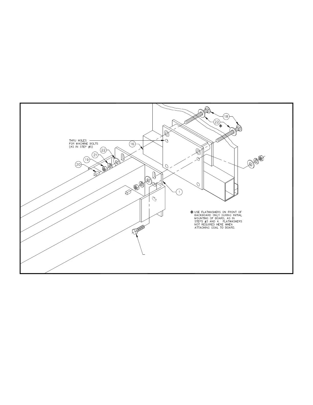
2. Position the unpacked glass backboard (#16) on its cardboard packing carton in front of portable backstop frame (#1). Remove
(2) 3/8" x 1" hex head cap screws from back of glass bank.
3. Assemble 3/8" x 3-1/2" bolt (#18) with 3/8" flatwasher (#22) in the upper two goal mount holes on the backboard. Note - This
hardware is packed with goal. Carefully lift backboard (#16) and position so that upper goal mounting bolts are in alignment with
the corresponding holes on the backstop mounting plate. See Illustration “A”. Three men are required to safely perform this
assembly. (Do not mount the goal at this time.)
4. While holding backboard in this position, secure in place on the backstop mounting plate (#1) with 3/8" hex nut (#19), 3/8"
lockwasher (#21) and 3/8" flatwasher (#22), finger tighten only.
5. Carefully shift backboard (pick one end up or down) to align slots shown in Illustration “A” with the two (2) tapped holes in the
backside of the backboard frame and secure with the two 3/8" x 1" long hex head cap screws (from No. 16) and 3/8" lockwashers
that were removed from the backboard in Step #2. Do not overtighten.
3/8" x 1-1/4" Lg. MACHINE BOLT, FLATWASHER,
LOCKWASHER AND HEX NUT SHIPPED
ASSEMBLED TO BACKBOARD
ILLUSTRATION "A"
 Loading...