7
6. Attach the two (2) hinge weldments (#3) into the slots in the upper corners of the glass backboard using four (4) 3/8" x 1-1/4"
long carriage bolts (#8), 3/8" hex nuts (#9), and 3/8" lockwashers (#11). Finger tighten only. See Illustration “B”.
7. The remaining assembly requires only to men. Lay bank yoke frame (#2) on the top side of the backstop horizontal extension
assembly positioning upper ends of the yoke into the hinges in the upper corner of the backboard assembled in Step #6. Secure in
place with two (2) 1/2" x 2-1/2" lg. hex head cap screws (#6), 1/2" hex nuts (#10), and 1/2" lockwashers (#12). Use 1/2"
flatwashers (#13) as spacers on either side of bank yoke frame stud (#2) (see Illustration “B”). Center the two hinge weldments
(#3) on the frame of the backboard and tighten all bolts securely.
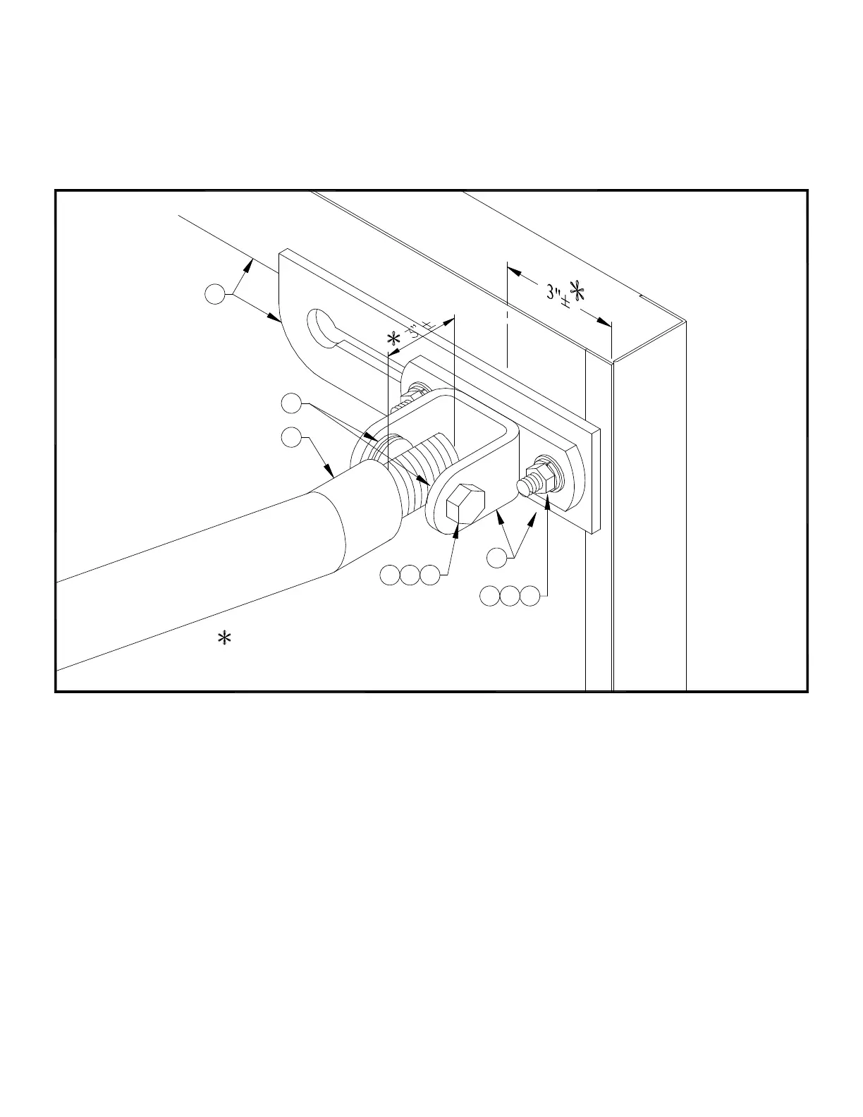
8. Attach lower end of bank yoke frame (#2) to the top tube of the horizontal extension assembly (see Illustration “C”) using two (2)
half clamps (#5), mounting plate (#4), and four (4) 3/8" x 5-1/2" hex head cap screws (#7), 3/8" hex nuts (#9), and 3/8"
lockwashers (#11). Snug bolts only at this time.
MUST BE CENTERED LEFT-TO-RIGHT
BACKBOARD YOKE FRAME/HINGE WELDMENTS
12
10 6
11
9
3
8
ILLUSTRATION "B"
16
13
2
STUDS MUST BE EXTENDED EQUALLY.
ON GLASS BACKBOARD FRAME.
 Loading...