8
9. Remove the two goal mounting bolts (#18, #19, #21, #22) assembled in Steps 3 & 4.
10. You are now ready to mount the goal. Carefully hold the goal (#17) against the face plate of the backboard (#16) and insert the
two bolts (#18) through the goal, backboard and the backstop mounting plate (refer back to Illustration “A”). Note - Flatwashers
are not required at this point. Backboard may have to be shifted slightly for proper alignment. Secure with two (2) 3/8" hex nuts
(#19), 3/8" flatwashers (#22), and two (2) 3/8" lockwashers (#21) on backside of mounting plate. Assemble two 3/8" plastic caps
(#20) on end of bolts.
11. Repeat Step 10 by inserting bolts through the bottom
two goal mounting holes. Snug bolts only at this time.
12. With the backstop in the down or folded position, roll the unit into the playing position, from end of court toward center court, so
that the two front swivel casters are facing the rear of the unit.
13. Raise the unit to the playing position and align the face of the backboard parallel to and 4′-0″ in from the inside edge
of the 2"
wide court line.
14. Marking the floor with tape, etc. will ensure proper alignment on future set-ups. Check anchor locations per anchor instructions.
15. Check Goal Height – Using a stepladder set goal height at 10' by adjusting the safety arm T-handle (see Illustration “D”). Lay
level across bottom of backboard while making this adjustment to insure that the backboard is level when the goal is at the 10'-0"
dimension. Note that it may be necessary to loosen the six (6) bolts in the backboard mounting plate very slightly to shift and
level the backboard. Re-tighten securely after final adjustments are complete. Goal height with shot clock installed (per shot
clock instructions), and T-handle disengaged, should be at 9′ 11-1/2". T-handle will raise goal height and place rear mast in
tension for maximum rigidity. NOTE – Unit will have to be checked again if the additional weight of a shot clock is added.
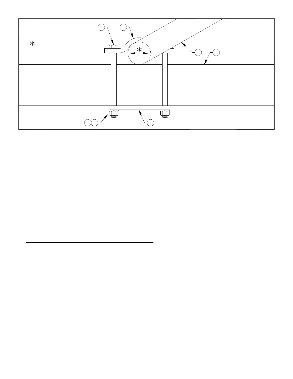
16. Lay a level vertically on the face of the glass backboard. Shift the clamp assembly on the rear of the bank yoke frame assembly
(see Illustration “C”) to properly plumb backboard. Tighten clamp bolts securely to hold backboard in position.
1
11
FRONT-TO-BACK TO PLUMB
ADJUST BACKBOARD YOKE FRAME
ILLUSTRATION "C"
FACE OF BACKBOARD
9
4
7 5
2
 Loading...